Eureka AIR delivers breakthrough ideas for toughest innovation challenges, trusted by R&D personnel around the world.

Propulsion unit for an aquatic vehicle having a mobile casing and a hydraulic fluid conditioning module

a technology of hydraulic fluid and propulsion unit, which is applied in the direction of marine propulsion, vessel construction, transportation and packaging, etc., can solve the problems of loss of lubricating properties, high stress on shaft bearings, and heating of hydraulic fluid contained in closed spaces

Active Publication Date: 2018-09-06
AETC SAPPHIRE
View PDF0 Cites 0 Cited by
  • Summary
  • Abstract
  • Description
  • Claims
  • Application Information

AI Technical Summary

Benefits of technology

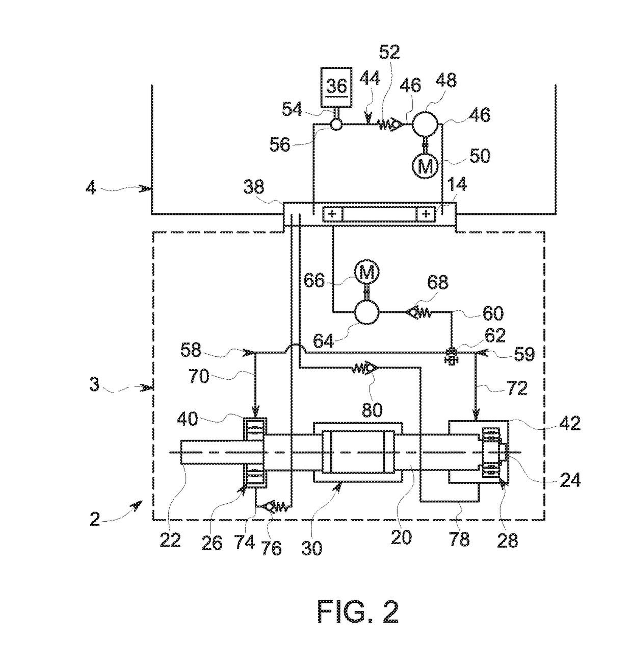
This patent aims to improve the conditioning of hydraulic fluid used in a propulsion unit for a mobile casing. The invention aims to reduce clutter and simplify the design, while also avoiding the need for ducts that may cause overpressure or premature wear. The solution involves using a single hydraulic fluid conditioning module and a circulation loop between the closed spaces of the shaft bearings and the azimuth bearing to allow for a continuous supply of cooled hydraulic fluid. This results in more efficient operation and reduced wear and tear on the sealing devices.

Problems solved by technology

The shaft bearings are often subjected to high stresses, in particular when the rotation of the drive shaft and the propulsion element occurs over long periods of time.
These stresses result in heating of the hydraulic fluid contained in the closed space and the loss of its lubricating properties.
This results in premature wear on the shaft bearings.

Method used


Image

  • Propulsion unit for an aquatic vehicle having a mobile casing and a hydraulic fluid conditioning module
  • Propulsion unit for an aquatic vehicle having a mobile casing and a hydraulic fluid conditioning module
  • Propulsion unit for an aquatic vehicle having a mobile casing and a hydraulic fluid conditioning module

Examples


Embodiment Construction

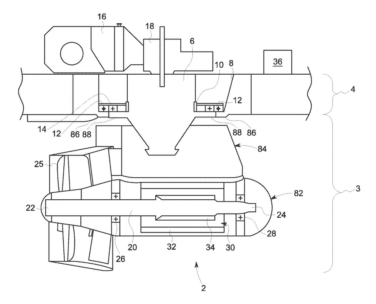
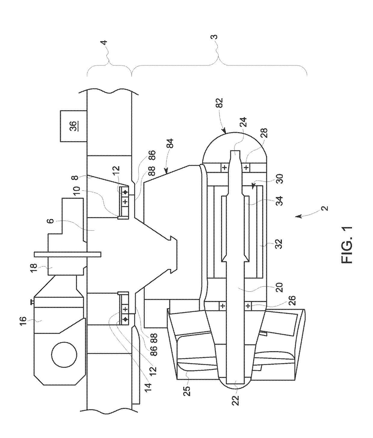
[0038]The propulsion unit 2 consists of an upper part 6 integral with the mobile casing 3 and inserted inside a bore 8 made in the hull element 4. The upper part 6 consists of a cylindrical portion 10. The bore 8 consists of a cylindrical portion 12 located facing the cylindrical portion 10. A rotary azimuth bearing 14 is arranged between the cylindrical portions 10 and 12. The azimuth bearing 14 may be e.g. a roller bearing having an inner ring (not shown) integral with the cylindrical portion 10, and an outer ring (not shown) integral with the cylindrical portion 12. A bearing space (not shown) is defined, radially located between the cylindrical portions 10 and 12. Within the bearing space are bearing elements (not shown), which may be rollers, balls or needles.

[0039]Alternatively, without departing from the scope of the invention, it is possible to envisage an azimuth bearing with a different design. For example, the azimuth bearing 14 may include bearing bushes. According to su...


PUM


Abstract

This propulsion unit for an aquatic vehicle consists of a mobile casing equipped with an azimuth bearing due to its mounting in a pivot connection in relation to a hull element of the aquatic vehicle, the azimuth bearing having a closed volume provided to contain a hydraulic fluid, the propulsion unit having a drive shaft of a propeller, said shaft being mounted rotatably within the mobile casing by means of at least one bearing having a closed space adapted to contain a hydraulic fluid, an electrical machine being adapted to drive the rotary drive shaft in relation to the mobile casing, the propulsion unit having a supply circuit adapted to supply the closed space of the shaft bearing with hydraulic fluid.The supply circuit has a supply duct connecting the closed space of the shaft bearing and the closed volume of the azimuth bearing.

Description

BACKGROUND TO THE INVENTION[0001]This invention relates to the field of propulsion units for aquatic vehicles, such as ships, submarines, or oil platforms.[0002]These propulsion units, also known as “Propulsion-Oriented Drive” or “POD”, generally consist of a mobile casing mounted in a pivot connection in relation to a hull element of the aquatic vehicle. The hull element may be e.g. the stern or the prow of a ship. The propulsion unit consists of a propulsion element, which may be e.g. a propeller, integral with a drive shaft rotatably mounted inside the mobile casing and capable of being rotated by means of an electrical machine.BRIEF DESCRIPTION OF THE INVENTION[0003]In order to provide the pivot connection between the mobile casing and the hull element, the propulsion unit consists of at least one rotary azimuth bearing. To limit friction, the azimuth bearing generally consists of a closed volume containing a hydraulic fluid, such as oil or water.[0004]In addition, rotary shaft ...

Claims


Application Information

Patent Timeline
Patent Type & Authority Applications(United States)
IPC IPC(8): B63H5/125F16C19/26F16C33/66
CPCB63H5/125F16C19/26B63H25/42B63H2005/1258F16C33/6659F16C2360/00B63H23/321B63H23/326F16C33/1045F16N7/40F16N7/00
Inventor JULLIAND, LIONELVINCENT, LOÏC
Owner AETC SAPPHIRE
Why Eureka
Eureka Blog
Learn More