Image processing apparatus
a technology of image processing and apparatus, applied in electrographic process apparatus, optics, instruments, etc., can solve the problems of difficult stabilization of communication with a communication apparatus in front of the casing, data transmitted in near-distance wireless communication cannot be received by one antenna, etc., and achieve the effect of enhancing communication accuracy
- Summary
- Abstract
- Description
- Claims
- Application Information
AI Technical Summary
Benefits of technology
Problems solved by technology
Method used
Image

Examples
first embodiment
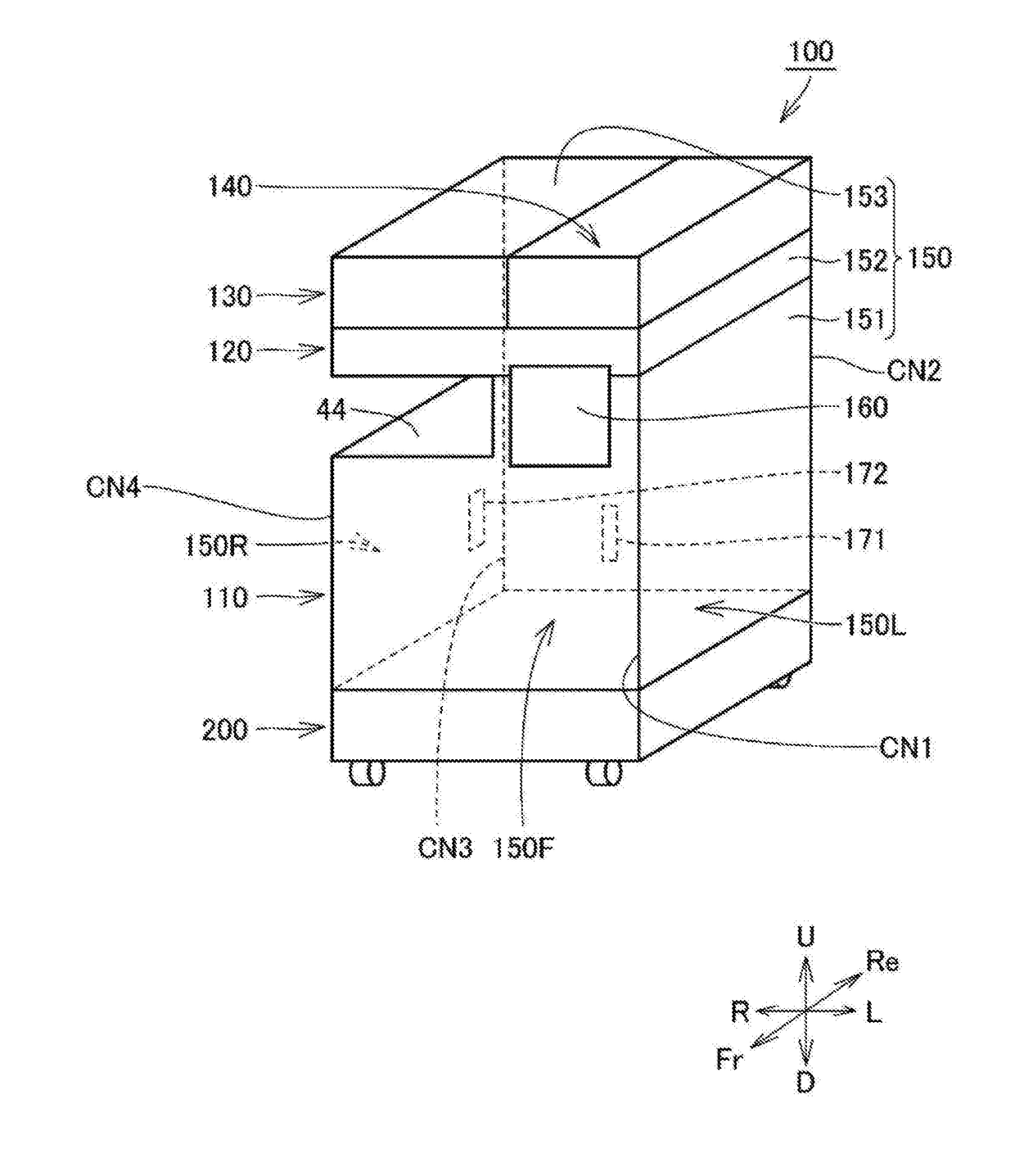
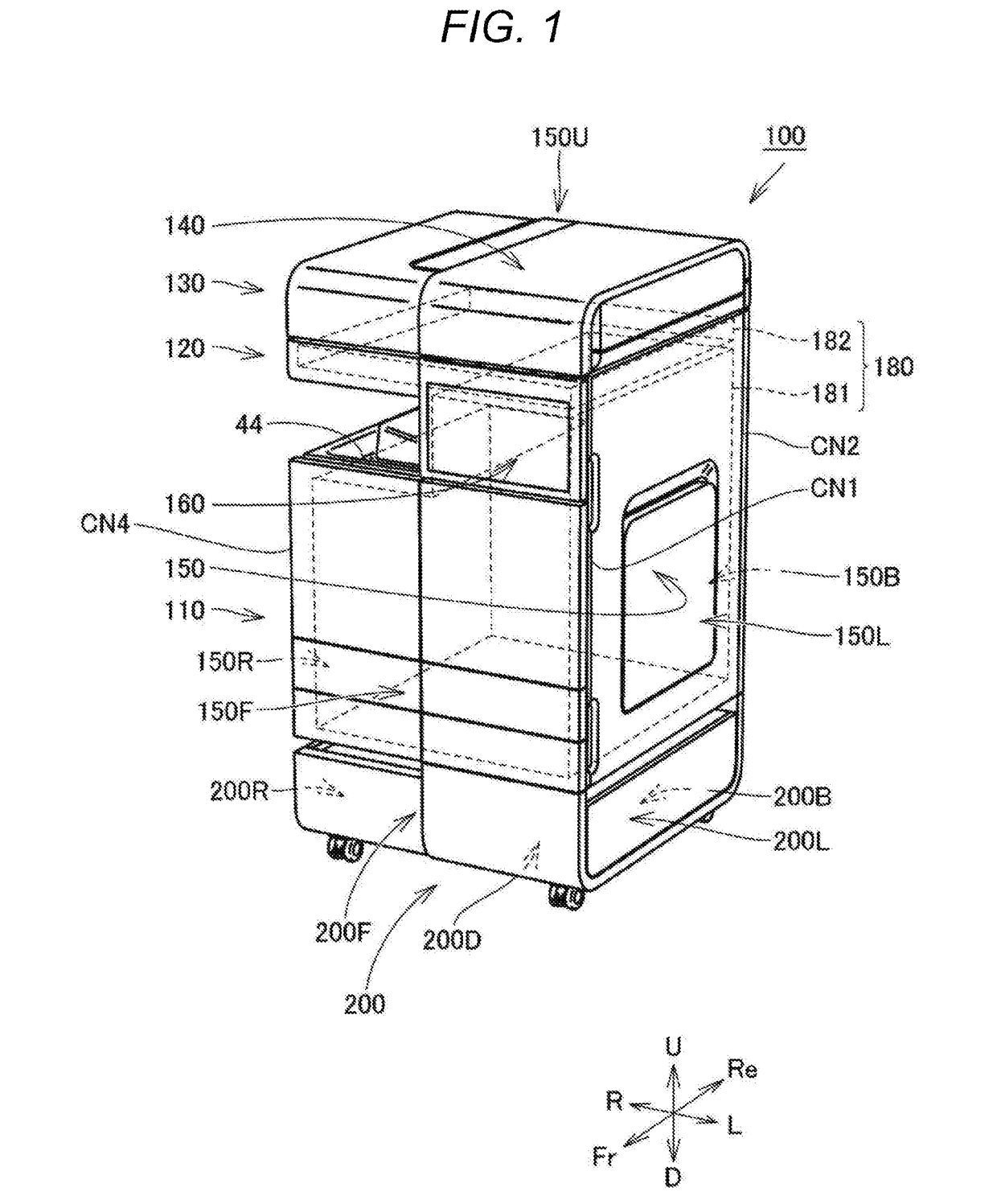
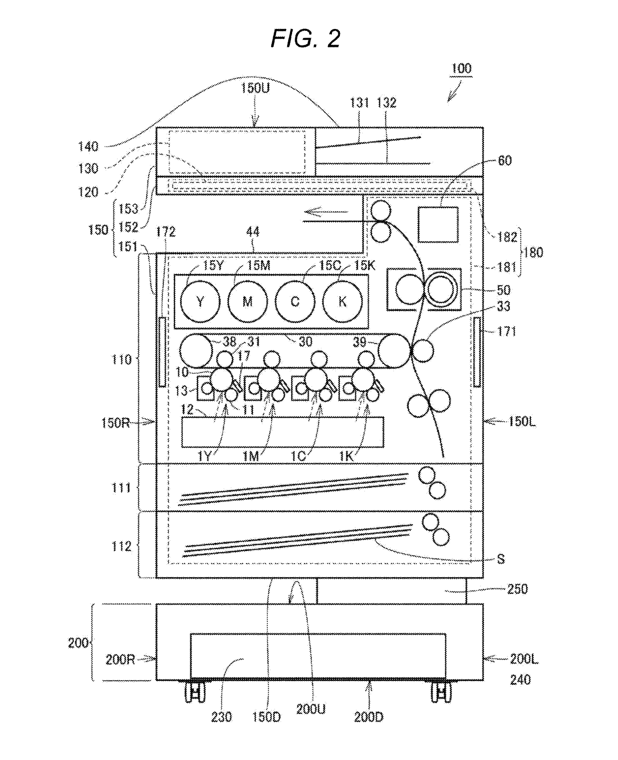
[0029]FIG. 1 is a perspective view of an image processing apparatus according to a first embodiment. FIG. 2 is a schematic diagram of the image processing apparatus according to the first embodiment. An image processing apparatus 100 according to the first embodiment will be described with reference to FIG. 1 and FIG. 2.
[0030]As illustrated in FIG. 1 and FIG. 2, the image processing apparatus 100 includes a casing 150, a first antenna 171 (see FIG. 2), a second antenna 172 (see FIG. 2), a shield member 180, and a server apparatus 200. The image processing apparatus 100 further includes an image former 110, an image reader 120, a document feeder 130, a cover member 140, and an operation panel 160.
[0031]The entire outer shape of the casing 150 is substantially a cuboid shape. The casing 150 includes a plurality of peripheries and a plurality of corners connecting mutually adjacent peripheries. Specifically, the casing 150 includes four peripheries and four corners.
[0032]The casing 150...
second embodiment
[0093]FIG. 9 is a schematic perspective view of an image processing apparatus according to a second embodiment. An image processing apparatus 100A according to the second embodiment will be described with reference to FIG. 9.
[0094]As illustrated in FIG. 9, the image processing apparatus 100A according to the second embodiment is different from the image processing apparatus 100 according to the first embodiment in a positional relationship between the first antenna 171 and the operation panel 160. Other constituents are almost similar.
[0095]The first antenna 171 is arranged above the operation panel 160. The operation panel 160 is arranged substantially at the center of the first casing part 151 in the vertical direction, for example. The operation panel 160 is arranged such that a user can touch the operation face while the user stands up with his / her hands down in consideration of operability of the user. The hands of the user can easily reach above the operation panel 160. Thereb...
third embodiment
[0099]FIG. 10 is a schematic perspective view of an image processing apparatus according to a third embodiment. An image processing apparatus 100B according to the third embodiment will be described with reference to FIG. 10.
[0100]As illustrated in FIG. 10, the image processing apparatus 100B according to the third embodiment is different from the image processing apparatus 100 according to the first embodiment in a position of the first antenna 171. Other constituents are almost similar.
[0101]The first antenna 171 and the second antenna 172 are arranged at the first corner (corner CN1) closest to the first antenna 171 and the second corner (corner CN3) closest to the second antenna 172, respectively.
[0102]The peripheries (the front face 150F and the left side face 150L) of the casing 150 which are mutually adjacent to form the corner CN1 and the peripheries (the back face 150B and the right side face 150R) of the casing 150 which are mutually adjacent to form the corner CN3 are mut...
PUM
 Abstract
Description
Claims
Application Information
 - R&D
- Intellectual Property
- Life Sciences
- Materials
- Tech Scout
- Unparalleled Data Quality
- Higher Quality Content
- 60% Fewer Hallucinations
Browse by: Latest US Patents, China's latest patents, Technical Efficacy Thesaurus, Application Domain, Technology Topic, Popular Technical Reports.
© 2025 PatSnap. All rights reserved.Legal|Privacy policy|Modern Slavery Act Transparency Statement|Sitemap|About US| Contact US: help@patsnap.com