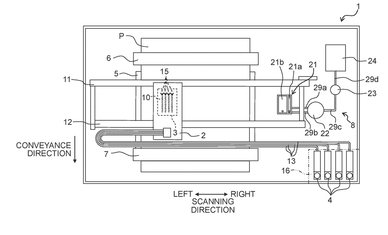
Liquid discharging apparatus
a liquid discharging and liquid technology, applied in the direction of printing, other printing apparatus, etc., can solve the problems of inability to calculate the ink jet printer described above has not calculated and the change in the viscosity of the mixed ink is not known, so as to achieve the effect of correct estimation of the viscosity of the mixed ink
- Summary
- Abstract
- Description
- Claims
- Application Information
AI Technical Summary
Benefits of technology
Problems solved by technology
Method used
Image
Examples
first modified embodiment
[0077]Alternatively, for example, in a first modified embodiment, as depicted in FIG. 7A, the ink tank 4 is provided with a light emitting element 101 and a light receiving element 102. The light emitting element 101 and the light receiving element 102 face each other in the scanning direction across a lower end portion of the ink tank 4. The light emitting element 101 radiates light toward the light receiving element 102.
[0078]If the ink residual amount in the ink tank 4 is more than a predetermined residual amount such that the ink level is positioned above the light emitting element 101 and the light receiving element 102, then the light radiated from the light emitting element 101 is blocked by the ink in the ink tank 4, so as not to reach the light receiving element 102. On the other hand, if the ink residual amount in the ink tank 4 is less than the predetermined residual amount such that the ink level is positioned below the light emitting element 101 and the light receiving ...
second modified embodiment
[0081]Further, as depicted in FIG. 7B, the ink tank 4 is provided with a plurality of light emitting elements 111 and a plurality of light receiving elements 112. The plurality of light emitting elements 111 are positioned at the left side of the ink tank 4 to align in the up / down direction. The plurality of light receiving elements 112 are configured to correspond to the plurality of light emitting elements 111 and positioned at the right side of the ink tank 4 to align in the up / down direction. By virtue of this, the light emitting elements 111 and the light receiving elements 112 correspond to each other and face each other in the scanning direction across the ink tank 4.
[0082]Then, with the group formed of each light emitting element 111 and the corresponding light receiving element 112, if the ink level in the ink tank 4 is positioned above the light emitting element 111 and light receiving element 112, then the light radiated from the light emitting element 111 is blocked by ...
third modified embodiment
[0085]Further, the method for estimating the residual ink viscosity Vr is not limited to that of the embodiment described above. For example, in a third modified embodiment, as depicted in FIG. 8, a printer 120 further includes a timer 121 (the “timer” of the present teaching). The timer 121 starts measuring time when the ink tank 4 is finished with the ink refill (for example, when the cover 16 is closed). When the ink tank 4 is newly refilled with the ink (for example, when the cover 16 is opened), the controller 50 acquires the elapsed time from the point of time of finishing the previous refill of the ink tank 4 with the ink on the basis of the measured result of the timer 121. Then, in the residual ink viscosity estimation process, the residual ink viscosity Vr is estimated on the basis of the above elapsed time, and the mixed ink viscosity Vm estimated at the time of the previous refill of the ink tank 4 with the ink. In particular, for the same mixed ink viscosity Vm estimate...
PUM
 Abstract
Description
Claims
Application Information
 - R&D
- Intellectual Property
- Life Sciences
- Materials
- Tech Scout
- Unparalleled Data Quality
- Higher Quality Content
- 60% Fewer Hallucinations
Browse by: Latest US Patents, China's latest patents, Technical Efficacy Thesaurus, Application Domain, Technology Topic, Popular Technical Reports.
© 2025 PatSnap. All rights reserved.Legal|Privacy policy|Modern Slavery Act Transparency Statement|Sitemap|About US| Contact US: help@patsnap.com


