
Sensor Arrangement for the Contactless Sensing of Angles of Rotation on a Rotating Part

a technology of rotating parts and sensors, applied in the direction of converting sensor output electrically/magnetically, instruments, measurement devices, etc., can solve the problem of complex electronics for coupling factor evaluation, and achieve the effect of low hardware complexity

Active Publication Date: 2018-08-23
ROBERT BOSCH GMBH
View PDF4 Cites 7 Cited by
  • Summary
  • Abstract
  • Description
  • Claims
  • Application Information

AI Technical Summary

Benefits of technology

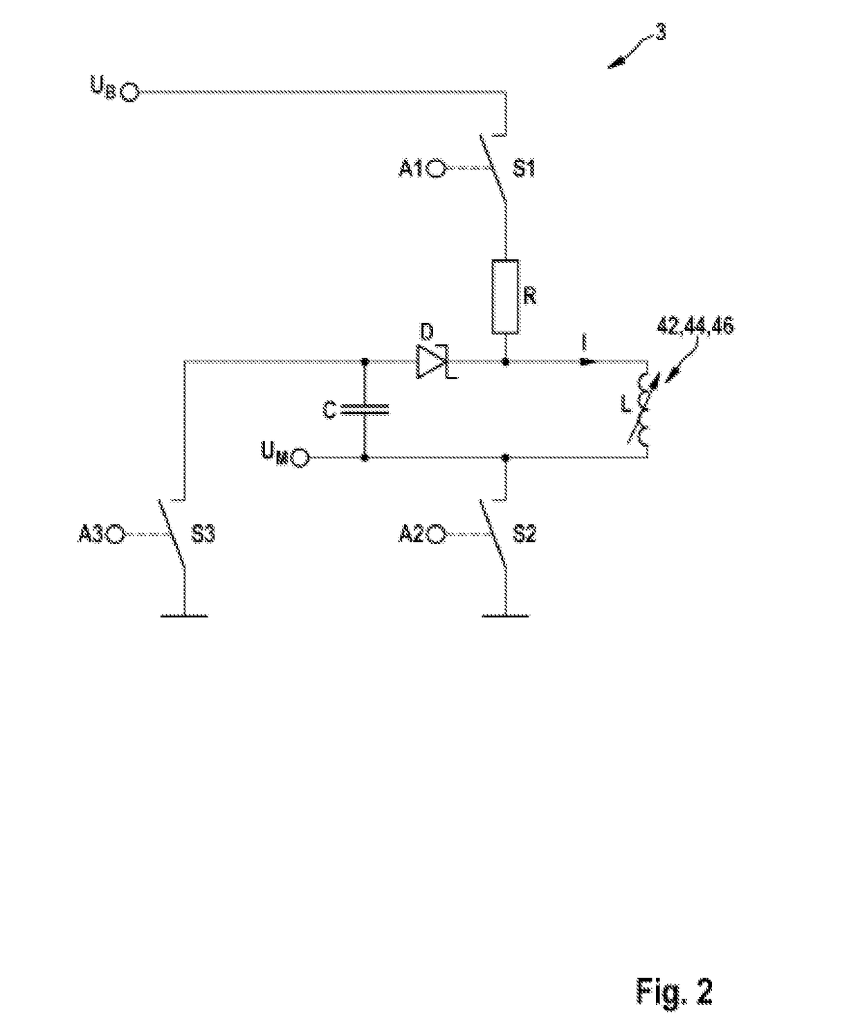
The present invention relates to a sensor arrangement for contactless sensing of angles of rotation. The sensor arrangement has the advantage of using a simple and economical evaluation method that converts magnetic energy into electrical energy. This evaluation method allows for the determination of the inductance of the detection coil using standard components such as transistors, diodes, and capacitors, in connection with a microcontroller that has an analog / digital converter. This results in a highly flexible and cost-effective sensor arrangement that can be easily integrated into designs for other functions. The technical effect of the invention is to provide a reliable and efficient solution for contactless sensing of angles of rotation.

Problems solved by technology

The evaluation of coupling factors requires complex electronics.

Method used


Image

  • Sensor Arrangement for the Contactless Sensing of Angles of Rotation on a Rotating Part
  • Sensor Arrangement for the Contactless Sensing of Angles of Rotation on a Rotating Part
  • Sensor Arrangement for the Contactless Sensing of Angles of Rotation on a Rotating Part

Examples


Embodiment Construction

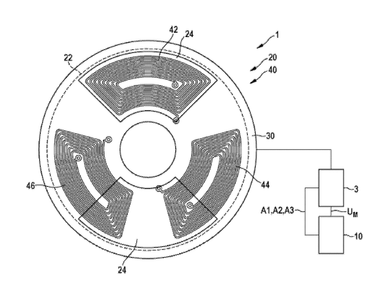
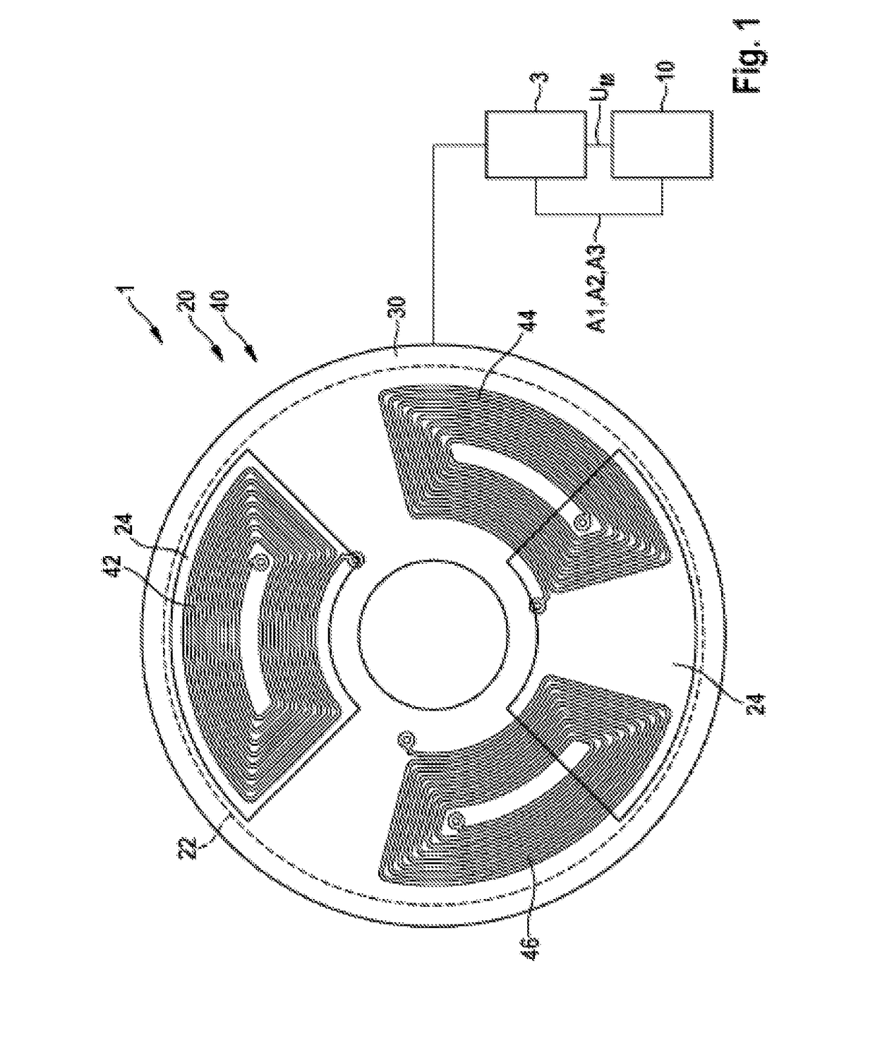
[0016]As is apparent from FIGS. 1 and 2, the depicted exemplary embodiment of a sensor arrangement 1 according to the present invention for the contactless sensing of angles of rotation on a rotating part includes a target 20 coupled with the rotating part, which has an annular disk-shaped base body 22 with at least one metal surface 24, and a coil arrangement 40 having at least one flat detection coil 42, 44, 46, which is arranged on a round printed circuit board 30. Of course, the printed circuit board 30 does not have to be round; the printed circuit board 30 may also have another suitable shape. In connection with the coil arrangement 40, the target 20 generates at least one piece of information for ascertaining the instantaneous angle of rotation of the rotating part. According to the present invention, at least one measuring circuit 3 converts the inductance L of a corresponding flat detection coil 42, 44, 46, which changes due to eddy-current effects, as a function of the deg...


PUM


Abstract

In one embodiment, a sensor arrangement for the contactless sensing of angles of rotation on a rotating part includes a disk-shaped target coupled to the rotating part. The disc-shaped target has at least one metal surface and generates at least one piece of information for ascertaining the instantaneous angle of rotation of the rotating part in connection with a coil arrangement. The coil arrangement has at least one flat detection coil. The arrangement further includes at least one measuring circuit that converts the inductance of a corresponding at least one flat detection coil into a measuring signal. The inductance changes due to eddy-current effects, as a function of the degree of overlap with the at least one metal surface of the rotating target. The arrangement further includes an evaluation and control unit that detects the measuring signal using measurement techniques and evaluates the signal for calculating the angle of rotation.

Description

[0001]The present invention is directed to a sensor arrangement for the contactless sensing of angles of rotation according to definition of the species in independent patent claim 1.[0002]The measurement of angles of rotation on rotating parts is generally carried out by using magnetic sensors. The rotating part to be measured is equipped with a permanent magnet. A corresponding magnetic field sensor which, for example, may be integrated into an integrated circuit, measures the field strength in two or three spatial directions and derives the angular orientation.[0003]In addition, various inductive rotational angle sensors are known from the related art. The coupling between an exciter coil and one or multiple sensor coils is largely influenced by the rotational angle position of a coupling element (target). The evaluation of coupling factors requires complex electronics.[0004]DE 197 38 836 A1 describes, for example, an inductive angle sensor including a stator element, a rotor ele...

Claims


Application Information

Patent Timeline
Patent Type & Authority Applications(United States)
IPC IPC(8): G01D5/20
CPCG01D5/2026G01D5/2013G01D5/202
Inventor LEIDICH, STEFANOBERLAENDER, JOERGKRAYL, OLIVER
Owner ROBERT BOSCH GMBH
Learn More