
System and method for locking and securing a firearm

a technology for locking and securing firearms, applied in the field of firearm locks, can solve the problems of inability to operate, loss or misplacement, affecting the reliability of firearms, etc., and achieve the effect of quick and easy removal of firearms

Inactive Publication Date: 2018-08-23
STOCKTON CHRIS
View PDF0 Cites 6 Cited by
  • Summary
  • Abstract
  • Description
  • Claims
  • Application Information

AI Technical Summary

Benefits of technology

The patent describes a locking device for firearms that can be easily unlocked by removing a padlock and a pin lock to release the firearm from its ejection port. The device also has an automatic unlocking feature that happens when the external padlock is removed from the pin lock tab and lock pin. The technical effect of this invention is to simplify the process of unlocking firearms, making them easier to remove and access.

Problems solved by technology

However, if the firearm is kept where it is accessible to children in the household the firearm should be stored in locked condition so that it cannot be operated without first removing the external locking device which secures it.
These locks often are not integral with the firearm, and accordingly, must be removed in order to render the firearm operable, and can thereby be lost or misplaced.
Prior locks for firearms which have been made to be integral with the firearm require extensive modification to the firearm, and thus can affect the reliability of the firearm and require time and expense for proper installation.
These firearm locks are sometimes difficult to manipulate, and therefore can be dangerous in an emergency where quick operation of the firearm is necessary.

Method used


Image

  • System and method for locking and securing a firearm
  • System and method for locking and securing a firearm
  • System and method for locking and securing a firearm

Examples


Embodiment Construction

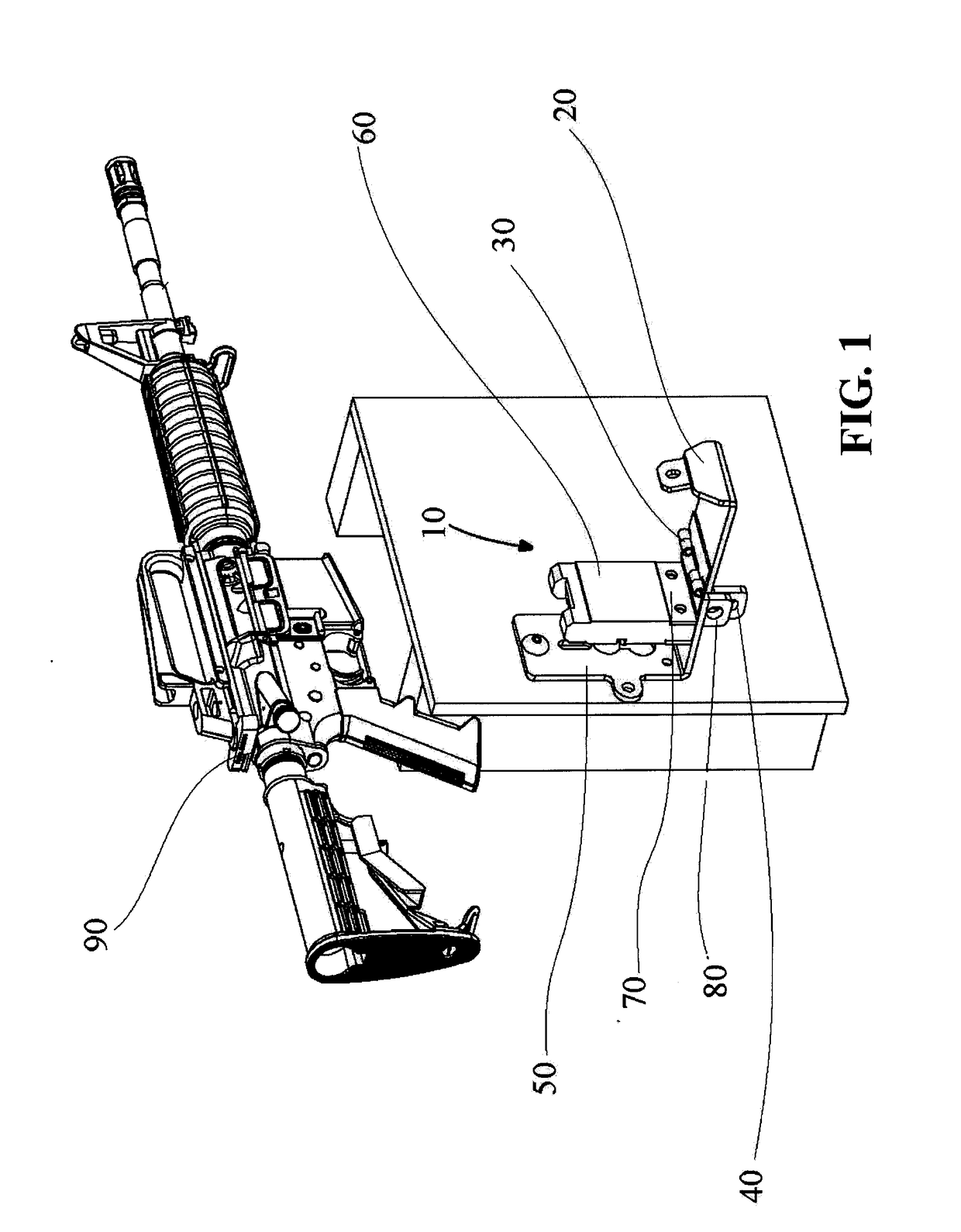
[0021]Referring to FIG. 1, a first preferred embodiment of a surface-mounted locking and securing device 10 for a firearm, according to the present invention, comprises a surface mounting bracket 50, a magazine block 60, and a lock bar 20. The mounting bracket 50 is attached to the lock bar 20 by a spring hinge 30 and comprises a mounting tab 70.

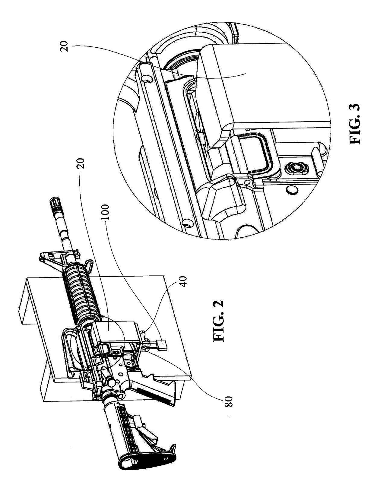
[0022]Still referring FIG. 1, the firearm 90 is secured to the device 10 via the magazine block 60 and the lock bar 20, when the lock bar 20 is in a closed position as shown in FIGS. 2-3.

[0023]FIG. 2 displays an external pad lock 100 is used to lock the spring-loaded lock pin 140 at a pin lock tab 40 and a mounting bracket lock tab 80 as shown in FIGS. 1 and 6. Additionally, FIG. 6 shows magazine mounting tab 70 being attached to the mounting bracket 50 to hold the magazine block 60 on the mounting bracket 50.

[0024]Referring to FIGS. 5-6, the device 10 is used to secure the firearm by locking the firearm within the magazine block 60, which i...


PUM


Abstract

A surface-mounted wall and / or vehicle locking and securing device for a firearm comprises a mounting bracket having a hinged lock bar connected at the second end of the mounting bracket. A magazine block is connected to the mounting bracket carrying a spring-loaded lock pin, which is dimensioned to pass through a hole or cut-out provided in the magazine block and the second end of the mounting bracket. A magazine mount tab is permanently attached to the mounting bracket for holding the magazine block. The device prevents the firearm from being loaded with ammunition and locks the firearm to a mounted surface using an external lock. The spring-loaded lock pin goes through the mounting bracket, magazine block inside the firearm and goes through a hole on the lock bar that comes through the firearm ejection port. The device has an automatic unlocking feature via a lock pin spring when the external padlock is removed from the pin lock tab and the lock pin. This allows the lock bar to automatically open for quick and easy removal of the firearm. Different external locks can be used to lock the firearm.

Description

BACKGROUND[0001]1. Field of Preferred Embodiment[0002]The present invention relates generally to a firearm lock, and more particularly, to a locking device for securing firearm.2. Background Art[0003]This invention relates generally to a safety device for firearm and deals more particularly with an improved lock for securing a firearm in a disabled or inoperative condition. A firearm used as a home defense weapon must be stored at a convenient location to be readily accessible in the event of emergency. However, if the firearm is kept where it is accessible to children in the household the firearm should be stored in locked condition so that it cannot be operated without first removing the external locking device which secures it.[0004]This invention is to prevent unauthorized access to a firearm. It locks the firearm to any secure surface (wall, Roll bar, vehicle etc.). The device locks the firearm to a surface as well as prevents the firearm from being loaded or fired when an exte...

Claims


Application Information

Patent Timeline
IPC IPC(8): F41A17/44
CPCF41A17/44A47B81/00
Inventor STOCKTON, CHRIS
Owner STOCKTON CHRIS
Learn More