Method, System, and Device for a Forward Vehicular Vision System

Inactive Publication Date: 2018-08-23
SMITH KEVIN ANTHONY
View PDF33 Cites 5 Cited by
  • Summary
  • Abstract
  • Description
  • Claims
  • Application Information

AI Technical Summary

Benefits of technology

The present invention is a new forward vehicular vision system that improves a driver's view by providing a better view of objects forward and alongside of the vehicle. This system achieves this by using image input apparatus to capture images of the forward field of view of the vehicle and displaying them on image output apparatus within the vehicle. The system can provide the driver with an enhanced visual field without requiring them to significantly direct the vehicle into an adjacent lane. The system can also be attached to the vehicle and can differentiate between any other views being displayed to create a distinction in the viewing perspective. Additionally, the system offers the driver a readily available forward field of view so that objects can be seen from a considerable distance without the need to move the vehicle significantly into an adjacent lane. The system can also incorporate conventional and modern vehicular vision system assembly configurations to optimize results for an enhanced forward view during operation of the vehicle.

Problems solved by technology

Many automobile accidents are consequences of human error rather than mechanical failure.
Vehicular accidents are commonly caused during the passing and overtaking of vehicles that are anterior to one's own vehicle.
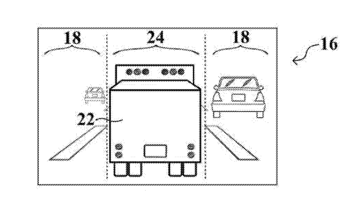
Safety hazards are created when large and / or wide vehicles block the visual field available to the vehicle in the posterior position, obstructing the view of the driver.
Moreover, fatalities often occur from head-on collisions on two-lane roadways where passing is permitted, from rear-end collisions during lane changes where traffic has stopped in adjacent lanes, and from side collisions during left turns at intersections of multi-lane roadways, when the oncoming traffic is not visible to the driver.
In particular, the driver's line of sight is more susceptible to obstruction by larger vehicles and prone to a blocked angle on the passenger side of the vehicle, making lane changes toward the passenger-side direction even more dangerous.
It is extremely problematic and presents a dangerous situation when drivers cannot see what is happening in front of them because a large vehicle, such as an SUV, van, bus, or truck, pulls in front of them on the roadway.
These large vehicles can block the driver's vision of the traffic further up the roadway.
The driver cannot get any advance warning by spotting brake lights of vehicles in a blocked angle beyond the large vehicle.
When a driver slows down, they must rely on the proper and timely braking of the large vehicle for warning of road hazards, as the driver cannot see the roadway in a blocked angle beyond the large vehicle obstructing their vision.
However, even with ‘defensive driving,’ where a driver leaves a car length between them and the vehicle in front of them for every 10 miles per hour they are traveling, the blocked angle is created by larger vehicles that obstruct the forward line of sight.
Prior art shows previous attempts at various image capture devices and control systems, but none address the targeted objectives described herein which presently indicate an unmet need that has yet to be offered on the market.
One of the most dangerous situations confronting law enforcement and emergency vehicles such as ambulances, fire trucks, and police cars, during high-speed emergency responses, is the lack of forward view due to a blocked angle.
Emergency responses often take place during high-traffic hours and may contain many obstructions alongside inclement weather and unpredictable road conditions.
This can create a problem when a quick response is necessary for a life-threatening situation.
These situations are very dangerous not only for the emergency and law enforcement vehicles, but civilian vehicles, as well.
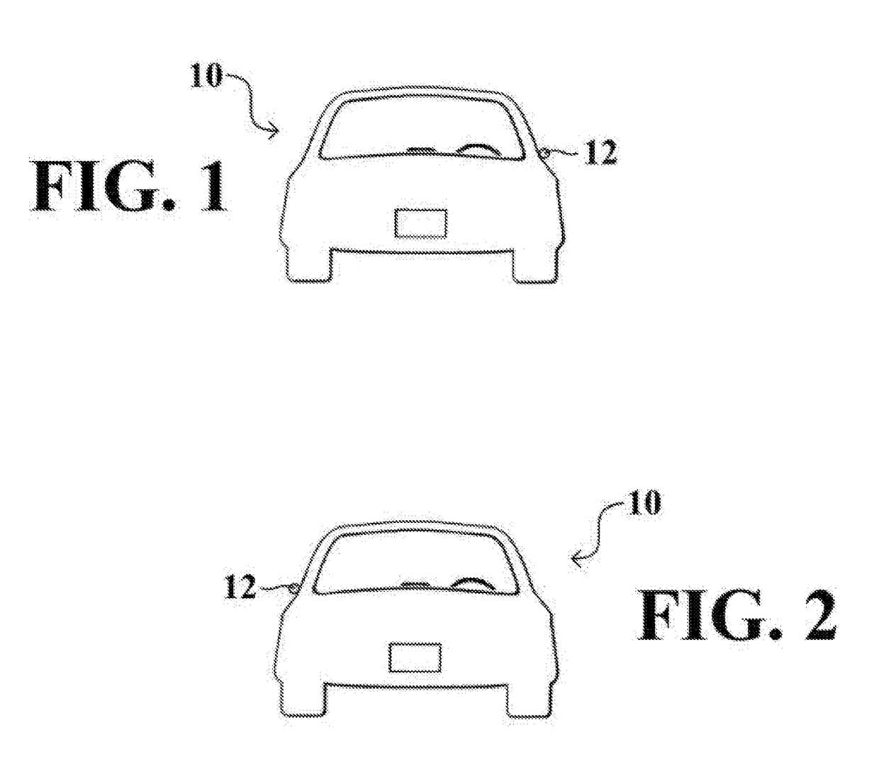
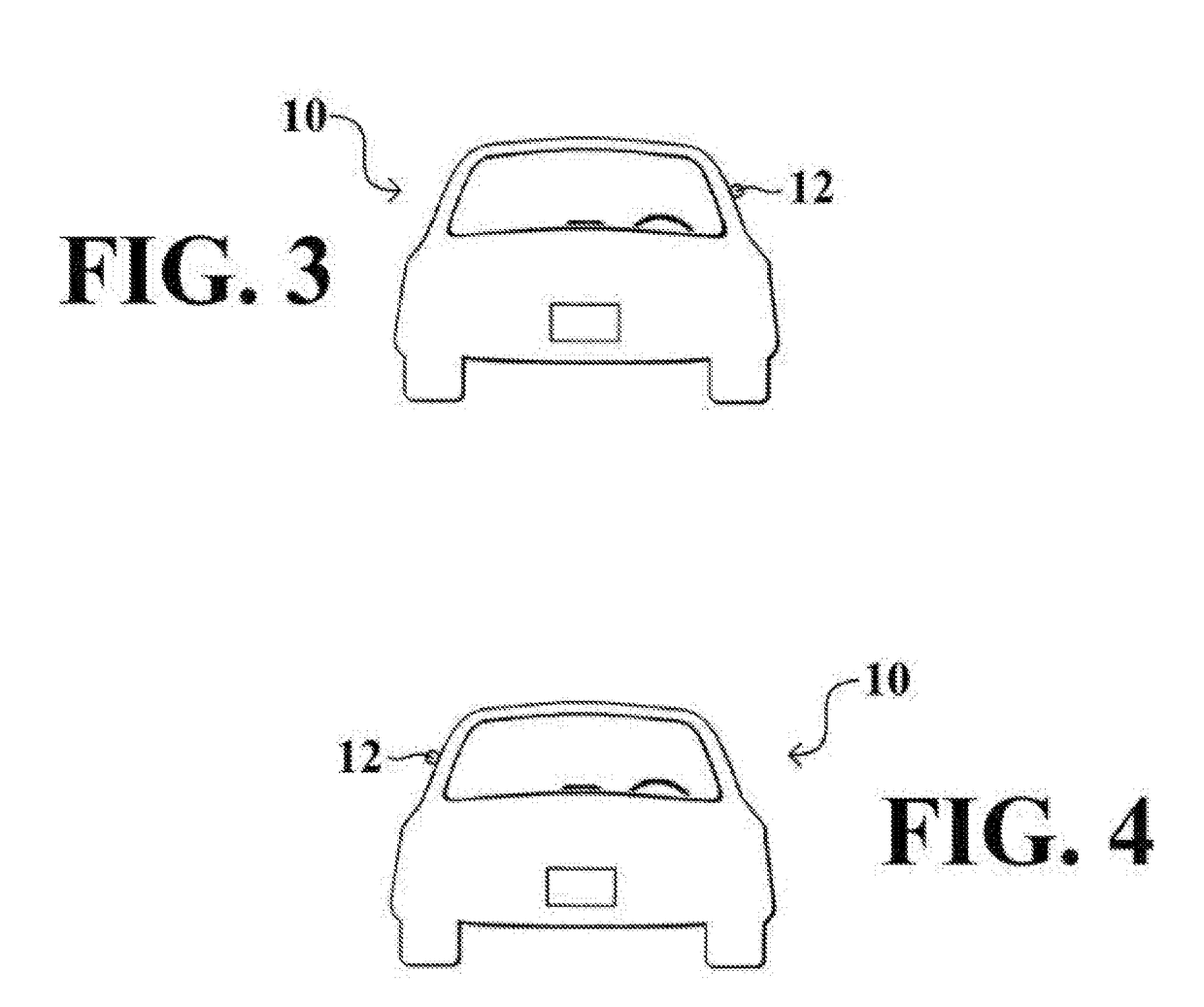
Furthermore, exterior mirrors protrude a substantial distance from the side of the vehicle, which makes maneuvering in tight spaces more difficult.
Exterior mirrors can impede driving when a driver cannot perceive vehicles, objects, or other road users in such blind spots without turning his or her body, which interferes with forward-looking visual activities.
Furthermore, where blind spot detection can be covered by these devices, having a vehicular vision system that displays a forward view, as opposed to only a predetermined and restricted detecting range, is necessary when traveling at high speeds of 30, 40, 50, and 60 mph because the forward adjacent lane may contain slow or stopped traffic which would not allow for a car having an obstructed view and changing lanes to decelerate in enough time to come to a complete stop, thus resulting in an accident.
The prior art displays many image capture and display systems that present views of the blind spots and surrounding areas of a vehicle that do not provide the necessary forward line of sight including areas in a blocked angle caused from an obstruction in front of a vehicle.
A constant display on a display system is more reliable as multiple views can crowd a display system, creating a visual burden and causing confusion as to which direction is being viewed by the driver.
Moreover, view selection adds operational burden to the driver if they have to select the view to be displayed.
Still, other prior art links a display system to the activity of a turn signal which can cause confusion on the roadway when used unnecessarily or excessively to check adjacent lanes.
Even still, other prior art uses side view mirrors which cause drag, wind noise, and lower fuel efficiency.
While these devices fulfill their respective, particular objectives and requirements, the aforementioned prior art does not disclose the present vehicular vision system.

Method used


Image

  • Method, System, and Device for a Forward Vehicular Vision System
  • Method, System, and Device for a Forward Vehicular Vision System
  • Method, System, and Device for a Forward Vehicular Vision System

Examples


Embodiment Construction

[0072]The present invention can be employed on automobiles such as cars, trucks and buses, and vehicles other than automobiles, as well as for commercial, emergency, military, and government vehicles, and for industrial uses such as on construction equipment or warehouse moving equipment. Other objects, features and advantages of the invention will become apparent from a consideration of the following detailed description and the accompanying drawings.

[0073]With reference now to the drawings, and in particular to FIGS. 1 through 42 thereof, a new forward vehicular vision system embodying the principles and concepts of the present invention will be described.

[0074]As best illustrated in FIGS. 1 through 42, the forward vehicular viewing system for a vehicle 10 generally comprises at least one optical instrument such as a camera, image sensor, fiber-optic apparatus, lensless compressive imaging architecture or other image input apparatus 12 and at least one display device such as a mon...


PUM


Abstract

A method, system, and device for a forward vehicular vision system, permitting a driver to view forward of the vehicle. The device provides the visual field forward of the vehicle and also extends the visual field to view areas, regions, and / or objects which are forward to allow a line of sight that might otherwise be blocked by an obstruction causing a blocked angle.

Description

CROSS-REFERENCE TO RELATED APPLICATION[0001]Not ApplicableFEDERALLY SPONSORED RESEARCH[0002]Not ApplicableREFERENCE TO SEQUENCE LISTING[0003]Not ApplicableFIELD OF THE INVENTION[0004]The present invention relates to vehicular viewing methods, systems, and devices and more particularly pertains to a new forward-viewing method, system, and device for vehicles.BACKGROUND OF THE INVENTION[0005]Many automobile accidents are consequences of human error rather than mechanical failure. This is especially true with today's state-of-the-art automotive amenities which have virtually eliminated the possibility of accidents occurring as a result of technological malfunction. Still, the automotive industry continues to focus on improved safety features for motor vehicles by designing mechanisms to protect both drivers and passengers, making for safer driving conditions.[0006]Vehicular accidents are commonly caused during the passing and overtaking of vehicles that are anterior to one's own vehicl...

Claims


Application Information

Patent Timeline
IPC IPC(8): B60R1/00H04N7/18H04N5/232
CPCH04N7/183B60R11/04B60R2300/802H04N5/23293B60R2300/30H04N23/63B60R1/24
Inventor SMITH, KEVIN ANTHONY
Owner SMITH KEVIN ANTHONY
Why Eureka
Try Eureka