
Medical device for temporary deployment into a bodily lumen

Active Publication Date: 2018-08-23
COOK MEDICAL TECH LLC
View PDF2 Cites 0 Cited by
  • Summary
  • Abstract
  • Description
  • Claims
  • Application Information

AI Technical Summary

Benefits of technology

The patent text describes a sheath assembly that has a seal assembly at the end to prevent blood from leaking out of it. This makes it easier to work with the sheath and to control the flow of blood during surgical procedures.

Problems solved by technology

The resultant interruption of blood flow increases stress on the heart, potentially causing cardiac morbidity.
Occlusion of blood flow also can lead to ischemia for downstream organs and extremities potentially leading to other complications.
Furthermore, the act of placing occlusive clamps across diseased blood vessels risks injury because the aorta itself is often diseased.
In addition, plaque along the arterial wall is potentially disturbed to embolise, which is highly undesirable.

Method used


Image

  • Medical device for temporary deployment into a bodily lumen
  • Medical device for temporary deployment into a bodily lumen
  • Medical device for temporary deployment into a bodily lumen

Examples


second embodiment

[0087]Because the medical device 200, according to the invention, does not rely on the tip 220 being extendable from the pusher 230 to stretch the temporary stent assembly 250, a pin vice assembly 280 (and its pin vice 283 and associated pin vice clamp) shown in FIG. 5 is not essential. FIG. 5A shows the medical device 200 without a pin vice assembly 280. Instead, a permanent retainer 284 is provided. This retainer 284 can be moulded into the handle 238 or attached in other ways.

[0088]Referring now to FIG. 5B, a diagrammatic cross-sectional view taken through section lines 5B-5B shown on FIG. 5A, it can be seen that the distal lines 262 of the temporary stent assembly 250 pass through a through bore 235 disposed around the guide wire cannula 210.

[0089]The line manipulator 290 is lockable in a deploying position in which the temporary stent assembly 250 is not stretched. FIGS. 5, 5A and 6 show the line manipulator 290 in its deploying position. Detent grooves 294 interact with proxim...

first embodiment

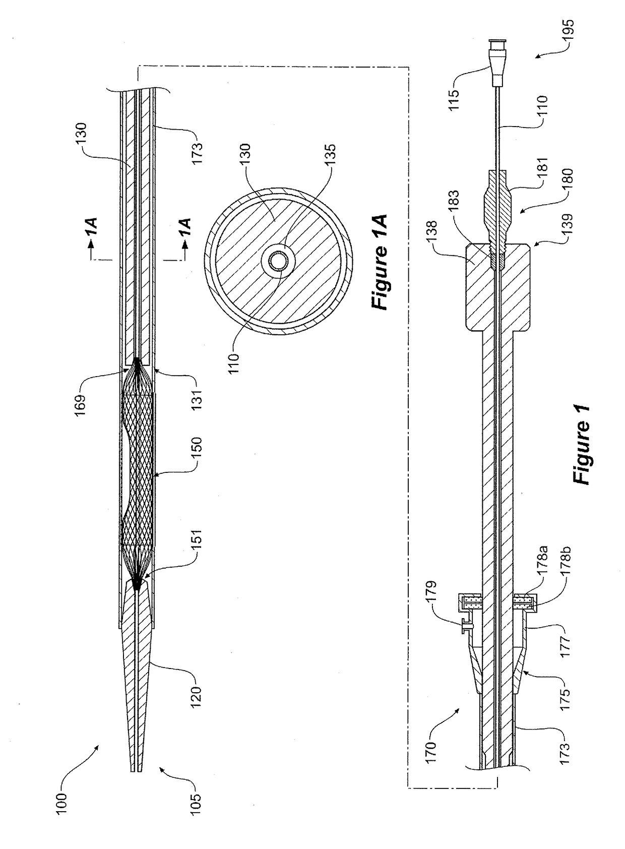
[0090]Now referring to FIG. 8, the device 200 is shown in its retracted position, the sheath assembly 270 having been moved in a proximal direction away from the handle 238 such that the sheath 273 covers the temporary stent assembly 250. The sheath assembly 270 is disposed over the pusher 230 in the same arrangement of the sheath assembly 170 and pusher 130 of the first embodiment described above. The sheath assembly 270 includes a sheath manipulator 275 of the distal end thereof. The sheath assembly includes a haemostatic seal assembly 177 (such as a Captor™ valve) and a flushing port 179, both at a distal end thereof.

[0091]A Luer lock connector 215 is also shown in FIGS. 5 to 8. As for the first embodiment of the invention, the Luer lock connector 215 allows flushing with sterile saline solution to eliminate air while the device 200 is outside of the patient.

[0092]The line manipulator 290 described above and illustrated in FIGS. 5 to 8 is just one example of a means for pulling t...


PUM


Abstract

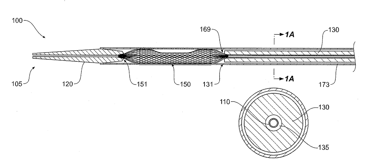
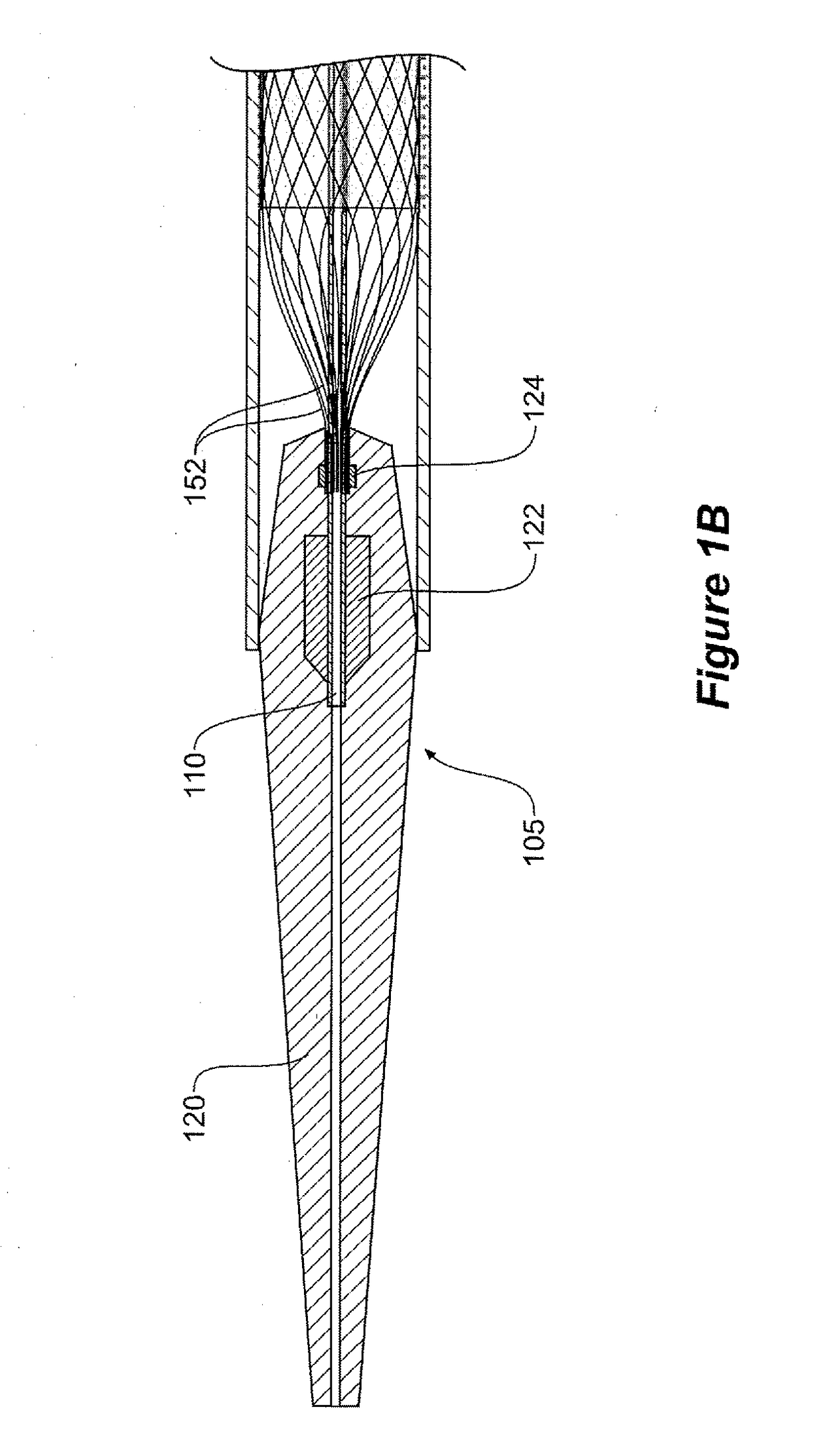
A medical device for temporary deployment into a bodily lumen is provided. The medical device comprises: a guide wire cannula having a proximal end and a distal end; a tip attached to the proximal end of the guide wire cannula; a pusher having a proximal and a distal end, the pusher having a through-bore disposed around the guide wire cannula; and a temporary stent assembly having a proximal end attached to the tip and a distal end adjacent to the proximal end of the pusher. The temporary stent assembly comprises a covered portion. The covered portion has a proximal sealing zone, a distal sealing zone and a recess between the proximal and distal sealing zones.

Description

TECHNICAL FIELD[0001]The present disclosure relates generally to the field of medical devices. Particular embodiments are related to medical devices that are deployable into bodily lumens including vascular systems.BACKGROUND OF THE INVENTION[0002]A variety of medical devices have been developed for endovascular repair. For instance various methods and devices have been developed to repair aneurysmal or occluded branches of the aorta. Devices and techniques have also been developed to bypass or cross-connect between adjacent arteries or other channels of the body. For instance, anastomosis procedures to join two or more arteries to that branch from the aortic arch are known. Commonly such techniques involve clamping and partial or total occlusion of aortic blood vessels. The resultant interruption of blood flow increases stress on the heart, potentially causing cardiac morbidity. Occlusion of blood flow also can lead to ischemia for downstream organs and extremities potentially lead...

Claims


Application Information

Patent Timeline
IPC IPC(8): A61B17/12
CPCA61B17/12109A61B17/1204A61F2/95A61B17/00234A61B17/3421A61F2/06A61F2/856A61F2/90A61F2002/823A61F2002/826A61B17/11A61B17/12045A61B17/12145A61B17/1215A61B2017/1107A61B2017/1139A61B2017/1205
Inventor BUDDERY, ALEXANDERGRIFFIN, JOSHUAWILKINSON, ROGER
Owner COOK MEDICAL TECH LLC
Learn More