
Vehicle stabilizer, processing device for eye portion of stabilizer, and processing method for eye portion

a technology for stabilizers and vehicles, applied in the field of stabilizers, can solve the problems of increased work, increased cost, and difficulty in accurately controlling the shape of eye portions,

Active Publication Date: 2018-08-16
NHK SPRING CO LTD
View PDF0 Cites 1 Cited by
  • Summary
  • Abstract
  • Description
  • Claims
  • Application Information

AI Technical Summary

Benefits of technology

The invention prevents distortion of the hole's reference surface when a trim portion is cut and a curved portion is punched, resulting in a more precise fastening surface for a vehicle stabilizer.

Problems solved by technology

When the eye portion of the stabilizer is to be formed by plastic working such as upsetting, there is a limit to accurately control the shape of the eye portion by the plastic working alone.
For example, it is difficult to accurately control, for example, the positional relationship between a distal end surface and a through-hole of the eye portion, and the flatness and the degree of parallelization of the fastening surface by the plastic working alone.
Accordingly, in order to increase the precision of the eye portion, finish processing such as machining is required, which means that work is increased and the cost thereby increased.
Because of the processing limit, etc., at the time of forming, obtaining a high-precision fastening surface was difficult in the eye portion of a conventional stabilizer.

Method used


Image

  • Vehicle stabilizer, processing device for eye portion of stabilizer, and processing method for eye portion
  • Vehicle stabilizer, processing device for eye portion of stabilizer, and processing method for eye portion
  • Vehicle stabilizer, processing device for eye portion of stabilizer, and processing method for eye portion

Examples


Embodiment Construction

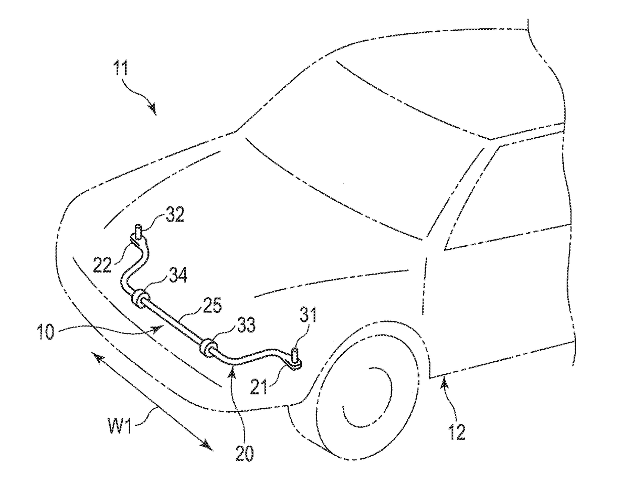
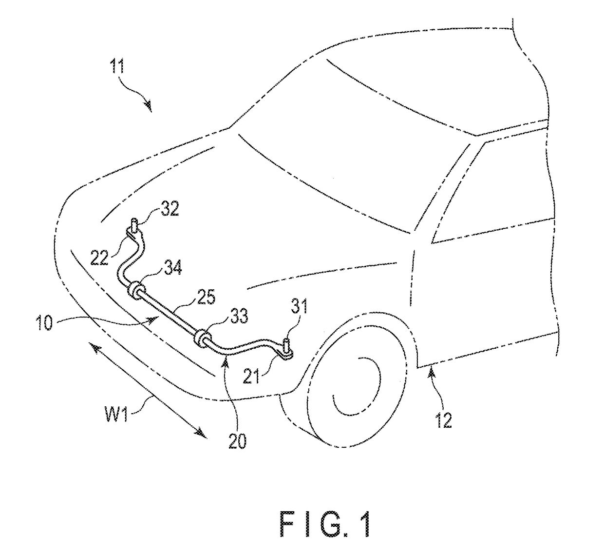
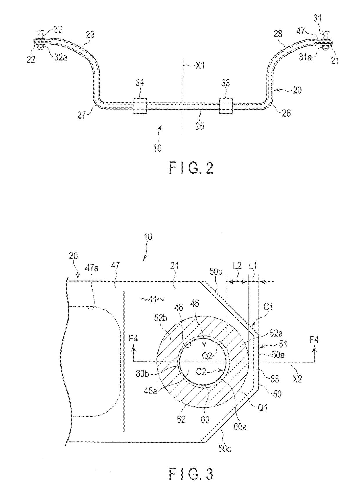
[0024]A stabilizer for a vehicle comprising an eye portion according to a first embodiment will be described with reference to FIGS. 1 to 4.

[0025]FIG. 1 shows a part of a vehicle 11 comprising a vehicle stabilizer (which may hereinafter be simply referred to as a stabilizer) 10. The stabilizer 10 constitutes a part of a suspension mechanism part arranged at the lower part of a vehicle body 12 of the vehicle 11. FIG. 2 is a plan view showing an example of the stabilizer 10.

[0026]The stabilizer 10 is formed of a rod-shaped steel material (for example, a steel pipe), and includes a stabilizer body portion 20, and a pair of eye portions 21 and 22 formed integrally on both ends of the stabilizer body portion 20. In the stabilizer 10, each of the eye portions 21 and 22 is formed by pressing an end portion of the steel pipe to be flat by plastic working such as forging. Accordingly, the stabilizer 10 includes the stabilizer body portion 20, which is hollow, substantially keeping the shape ...


PUM

PropertyMeasurementUnit
Lengthaaaaaaaaaa
Distanceaaaaaaaaaa

Abstract

An annular reference surface is formed around a through-hole of an eye portion. A distal-end-side curved portion is formed at a first corner portion, on an outer side of the annular reference surface. The thickness of the distal-end-side curved portion is reduced in a range of a length from the first flat surface toward the distal end surface. A hole-side curved portion whose thickness is reduced toward an inner surface of the through-hole is formed at a second corner portion, on an inner side of the annular reference surface. The length of the hole-side curved portion is less than the length of the distal-end-side curved portion. The hole-side curved portion is curved with a greater curvature than that of the distal-end-side curved portion.

Description

CROSS-REFERENCE TO RELATED APPLICATIONS[0001]This application as a Continuation Application of PCT Application No, PCT / JP2016 / 079860, filed Oct. 6, 2016 and based upon and claiming the benefit of priority from prior Japanese Patent Application No. 2015-206589, filed Oct. 20, 2015, the entire contents of all of which are incorporated herein by reference.BACKGROUND OF THE INVENTION1. Field of the Invention[0002]The present invention relates to a vehicle stabilizer arranged in a suspension mechanism part of a vehicle such as a car, a processing device for an eye portion of the stabilizer, and a method for processing the eye portion.2. Description of the Related Art[0003]A stabilizer arranged in a suspension mechanism part of a vehicle, which is formed of a steel pipe or a solid rod-shaped steel material, includes a torsion portion (a twisted portion) which extends in a width direction of the vehicle, and a pair of arm portions (arms) connected via bent portions on both ends of the tors...

Claims


Application Information

Patent Timeline
IPC IPC(8): B60G21/055B60G21/00B60G21/02
CPCB60G21/055B60G21/005B60G21/026B60G2206/017B60G2206/83B60G2206/427B60G2206/724B60G2206/81022B60G2206/8103B60G2206/811B21J5/022B21J5/027B21J9/12B21K21/14B21J9/04B21K21/12B21D53/88B21J5/02B21J5/10B21D45/006B21D28/02B21D28/24
Inventor SAKURAI, YASUHARUKOSHITA, YOSHIHIRONISHIKAWA, AKIHIKOOTANI, AKIFUMI
Owner NHK SPRING CO LTD
Learn More