
Wiring structure for electronic apparatus and image forming apparatus

Active Publication Date: 2018-08-02
CANON KK
View PDF0 Cites 0 Cited by
  • Summary
  • Abstract
  • Description
  • Claims
  • Application Information

AI Technical Summary

Benefits of technology

This patent describes a way to attach a magnetic component to an electronic device and make it easier to hold. This invention is useful for creating an image forming apparatus.

Problems solved by technology

With this configuration, however, the ferrite cores might fall out of the holder when the holder is elastically deformed by causes such as external shock caused by vibration or dropping of the apparatus.
Further, if the stiffness of the holder is increased to enhance the holding ability of the ferrite core, there may be drawbacks such as the deterioration of workability in attaching the ferrite core, or damaging of the ferrite core by reaction force received from the holder in a case of attaching the ferrite core.

Method used


Image

  • Wiring structure for electronic apparatus and image forming apparatus
  • Wiring structure for electronic apparatus and image forming apparatus
  • Wiring structure for electronic apparatus and image forming apparatus

Examples


first embodiment

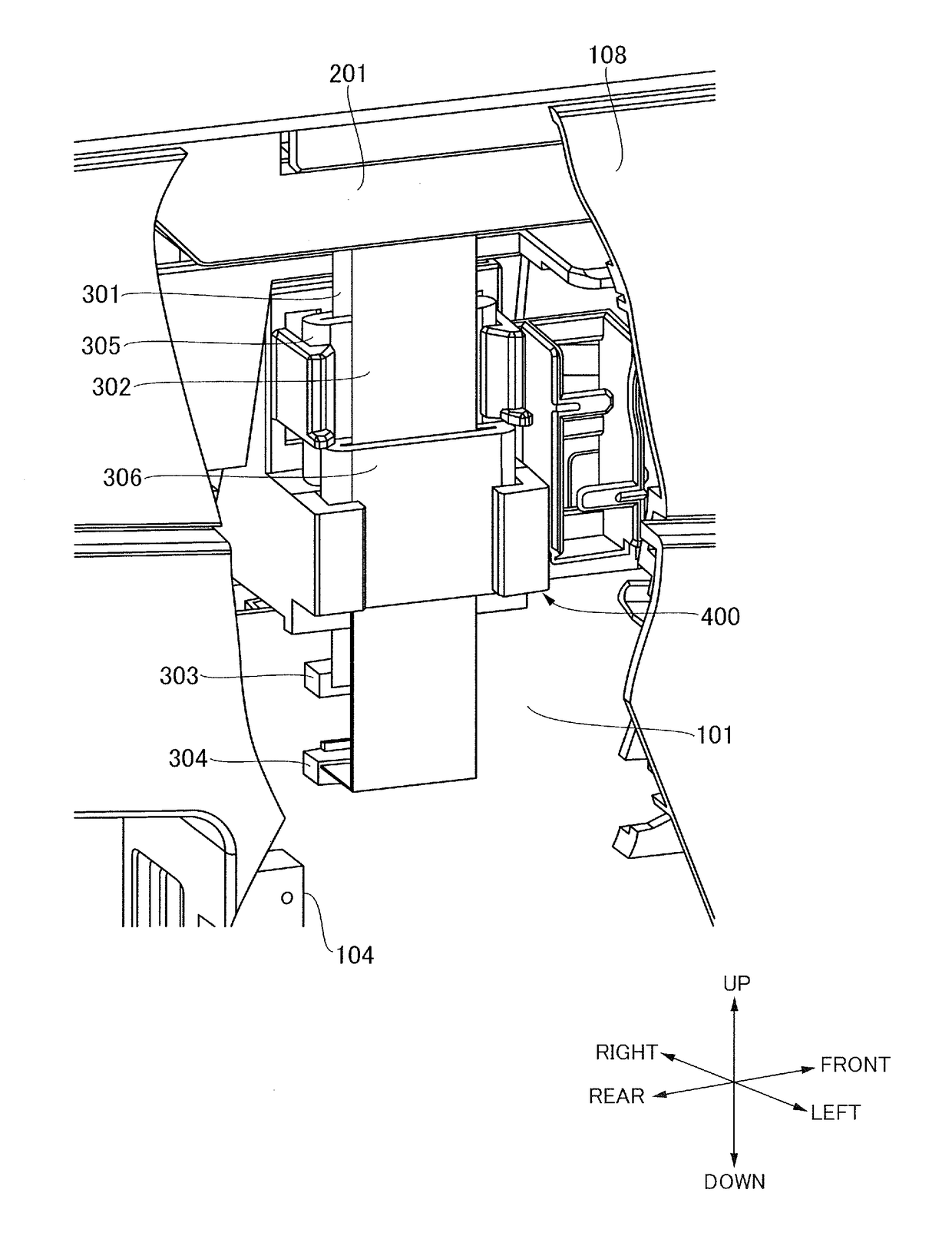
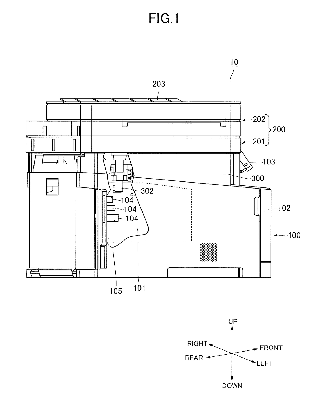
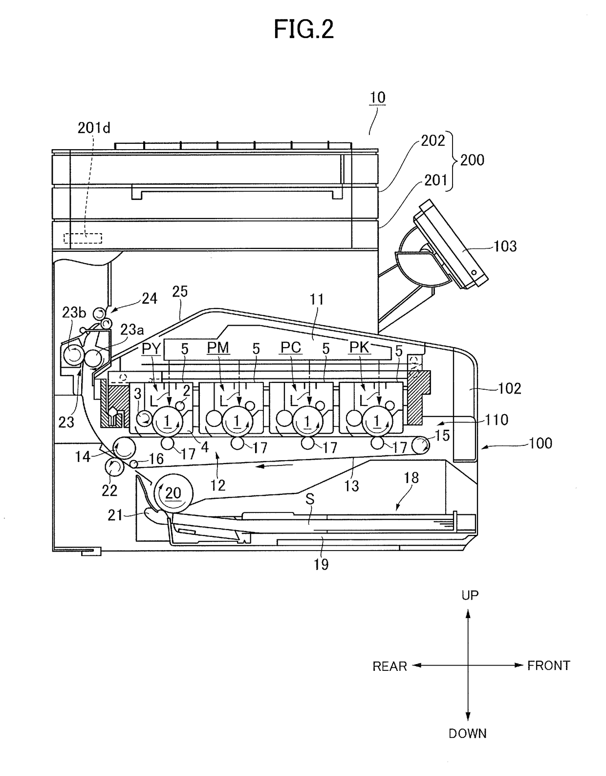
[0026]As illustrated in FIG. 1, an image forming apparatus 10 according to a first embodiment includes an apparatus body 100, which houses an image forming unit to form an image on a sheet that serves as a recording medium, and an image reading unit 200 configured to read image information from a sheet that serves as an original, or a document. A sheet may be, in addition to plain paper, special paper such as coated paper, recording material having a special shape such as an envelope or an index paper, a plastic film such as an OHP film, cloth, and so on.

[0027]A door 102 capable of opening an inner side of the apparatus body 100 and an operation display portion 103 equipped with an operation panel serving as user interface are provided on one side portion of the image forming apparatus 10. In the following description, the side on which the door 102 and the operation display portion 103 are arranged with respect to the image forming apparatus 10 is referred to as “front” or “front s...

second embodiment

[0068]Next, a wiring structure according to a second embodiment will be described with reference toFIGS. 12A and 12B. The wiring structure according to the present embodiment differs from that of the first embodiment in that interposed members 49f and 49r that function as spacers between the two ferrite cores 305 and 306 are arranged on the elastic hooks 43f and 43r. The other configurations are similar to the first embodiment, so elements that are common to the first embodiment are denoted with the same reference numbers, and descriptions thereof are omitted.

[0069]As illustrated in FIGS. 12A and 12B, a holder 410 serving as a holder according to the present embodiment includes the first holding portion 401 to hold the first ferrite core 305 and the second holding portion 402 to hold the second ferrite core 306. Similar to the first embodiment, the ferrite cores 305 and 306 are held in a state partially overlapping with one another when viewed from the left, and movement of the firs...


PUM


Abstract

A holder holds a first magnetic member through which the first signal cable is passed and a second magnetic member through which the second signal cable is passed. The holder holds the first magnetic member with a first holding portion including an elastic engagement portion. The holder is also provided with a second holding portion to hold the second magnetic member at a position where the second magnetic member overlaps with the first magnetic member. A restrict portion is arranged on the elastic engagement portion and configured to restrict movement of the second magnetic member held by the second holding portion.

Description

BACKGROUND OF THE INVENTIONField of the Invention[0001]The present invention relates to a wiring structure for an electronic apparatus including a noise filter, and an image forming apparatus equipped with the wiring structure.Description of the Related Art[0002]It has been known that noise transmitted through a signal cable wired inside an electronic apparatus can be reduced by attaching a magnetic member such as a ferrite core to the signal cable. Japanese Unexamined Patent Application Publication No. H02-308609 discloses attaching a cylindrical ferrite core to an interface cable wired inside a keyboard, and holding the ferrite core by an elastic holding claw. According to this arrangement, the holding claw is elastically deformed when the ferrite core is pushed in, so that the holding claw retains the ferrite core.[0003]Japanese Unexamined Patent Application Publication No. 2011-205335 discloses a configuration where signals conveying image information read by two contact image s...

Claims


Application Information

Patent Timeline
IPC IPC(8): G03G15/00H01F27/26H03H1/00H01B7/08H05K1/02
CPCH01F27/266H03H1/0007H01B7/08H05K1/028G03G15/80H03H2001/0092H01F17/06H01F2017/065H04N1/00559H04N1/0083H04N2201/0094
Inventor ONISHI, MASASHI
Owner CANON KK
Learn More