
Heat dissipation circuit board and method for producing heat dissipation circuit board

Inactive Publication Date: 2018-07-26
SUMITOMO ELECTRIC IND LTD +1
View PDF0 Cites 4 Cited by
  • Summary
  • Abstract
  • Description
  • Claims
  • Application Information

AI Technical Summary

Benefits of technology

The present invention provides a heat dissipation circuit board and a method for producing it that can effectively promote heat dissipation from mounted electronic components, resulting in reliable insulation. This makes it suitable for use in LED lighting apparatuses, providing better performance and reliability.

Problems solved by technology

Some electronic components mounted on printed circuit boards, such as light-emitting diodes (LEDs), generate a large amount of heat during operation.

Method used


Image

  • Heat dissipation circuit board and method for producing heat dissipation circuit board
  • Heat dissipation circuit board and method for producing heat dissipation circuit board
  • Heat dissipation circuit board and method for producing heat dissipation circuit board

Examples


first embodiment

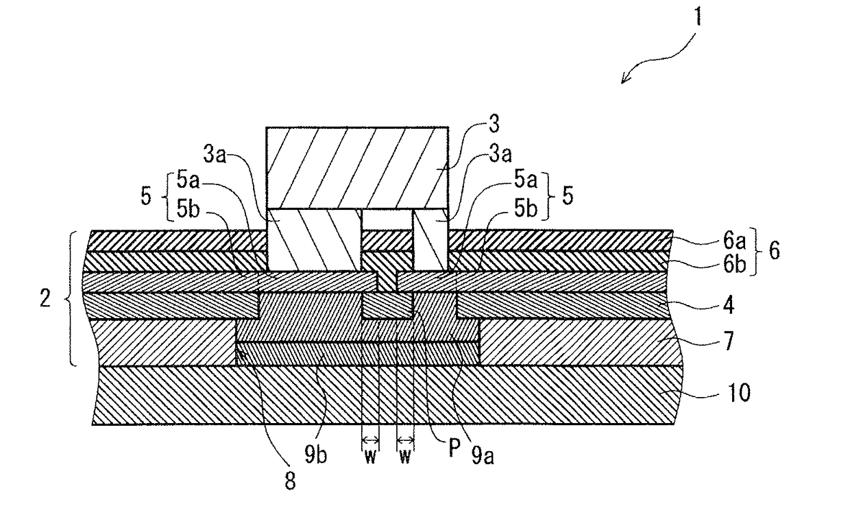
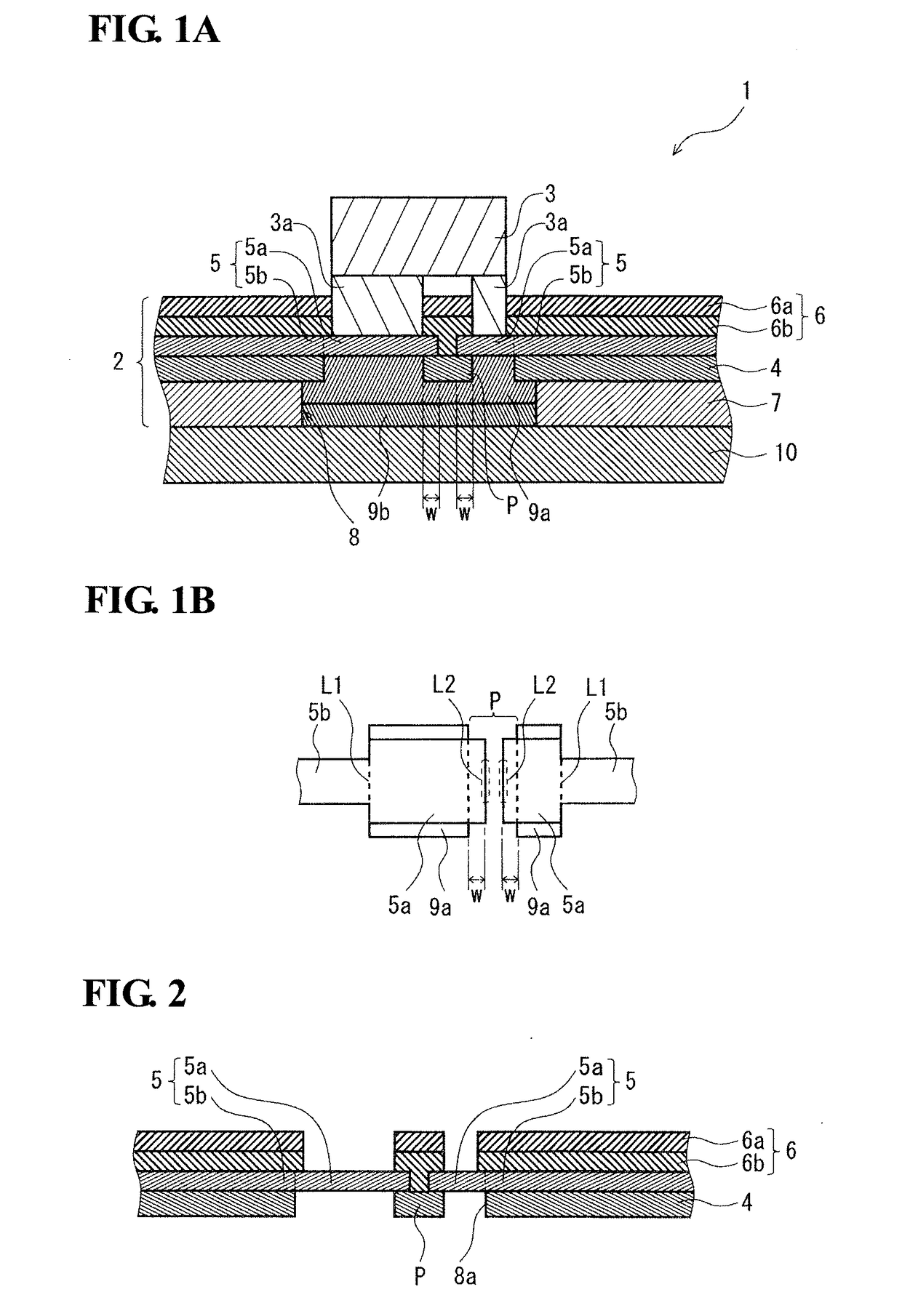
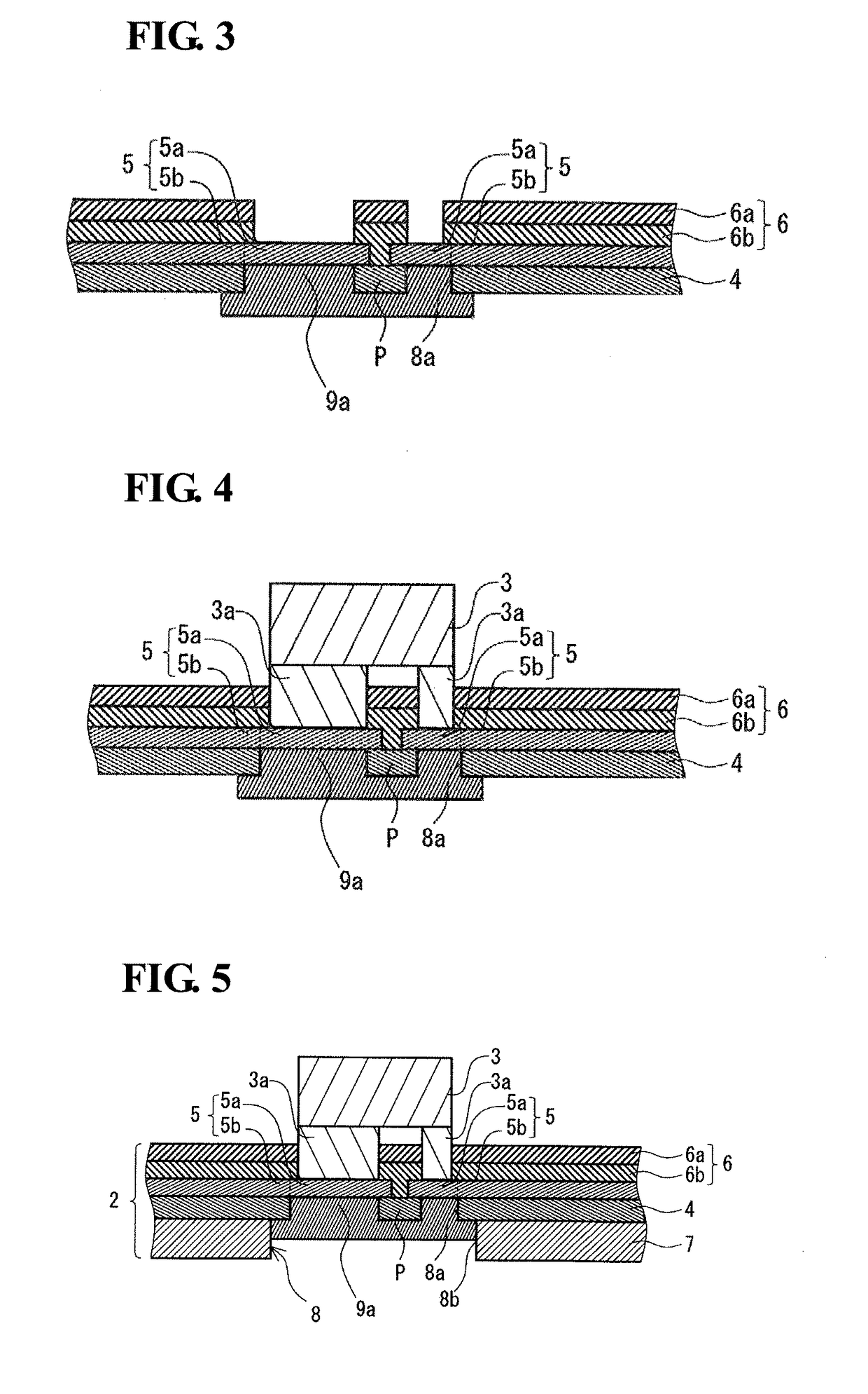
[0038]A heat dissipation circuit board 1 illustrated in FIG. 1A mainly includes a flexible printed circuit board 2 having flexibility, a light-emitting diode 3 mounted on this flexible printed circuit board 2, and a thermally conductive base member 10 disposed on the back-surface side of the flexible printed circuit board 2.

[0039]The flexible printed circuit board 2 includes an insulating film 4; a conductive pattern 5 disposed on the front-surface side of this insulating film 4 and including plural land parts 5a on which the light-emitting diode 3 is mounted and wiring parts 5b connected to the land parts 5a; a coverlay 6 disposed on the front surfaces of the insulating film 4 and the conductive pattern 5; and an adhesive layer 7 disposed on the back surface of the insulating film 4. This flexible printed circuit board 2 includes a recess 8 on a side opposite to a side on which the light-emitting diode 3 is mounted, the recess 8 being in at least a portion of the projection region ...

second embodiment

[0101]A heat dissipation circuit board 11 illustrated in FIG. 7 mainly includes a flexible printed circuit board 2 having flexibility, a light-emitting diode 3 mounted on this flexible printed circuit board 2, and a thermally conductive base member 10 disposed on the back-surface side of the flexible printed circuit board 2. This flexible printed circuit board 2 includes a recess 18 on a side opposite to a side on which the light-emitting diode 3 is mounted, the recess 18 being in at least a portion of the projection region of land parts 5a, the recess 18 extending to a conductive pattern 5. This recess 18 is filled with thermally conductive adhesive layers 9a and 9b. The flexible printed circuit board 2 in the heat dissipation circuit board 11 in FIG. 7 is the same as the flexible printed circuit board 2 in the heat dissipation circuit board 1 in FIG. 1 except for the recess 18. The light-emitting diode 3 and the thermally conductive base member 10 are the same as in the heat dissi...

third embodiment

[0105]A heat dissipation circuit board 21 illustrated in FIG. 8 mainly includes a flexible printed circuit board 2 having flexibility, plural light-emitting diodes 3 mounted on the flexible printed circuit board 2, and a thermally conductive base member 20 disposed on the back-surface side of the flexible printed circuit board 2. The flexible printed circuit board 2 includes recesses 8 on a side opposite to a side on which the light-emitting diodes 3 are mounted, the recesses 8 being in at least portions of the projection regions of land parts 5a, the recesses 8 extending to a conductive pattern 5. These recesses 8 are filled with thermally conductive adhesive layers 9a and 9b. The flexible printed circuit board 2 and the light-emitting diodes 3 in the heat dissipation circuit board 21 in FIG. 8 are the same as in the heat dissipation circuit board 1 in FIG. 1. Accordingly, the same reference signs are used and redundant descriptions will be omitted.

[0106]The thermally conductive ba...


PUM


Abstract

A heat dissipation circuit board includes a printed circuit board including an insulating film and a conductive pattern that is formed on a front-surface side of the insulating film and includes at least one land part and a wiring part connected to the at least one land part; and at least one electronic component mounted on a front-surface side of the at least one land part. In the heat dissipation circuit board, the printed circuit board includes a recess on a side opposite to a side on which the at least one electronic component is mounted, the recess being in at least a portion of a projection region of the at least one land part, the recess extending to the conductive pattern, and includes a thermally conductive adhesive layer filling the recess. Furthermore, in the heat dissipation circuit board, the insulating film remains, in plan view, in a region including, in the at least one land part, at least a portion of a connecting boundary to the wiring part or at least a portion of a peripheral edge facing the connecting boundary.

Description

TECHNICAL FIELD[0001]The present invention relates to a heat dissipation circuit board and a method for producing a heat dissipation circuit board.BACKGROUND ART[0002]Some electronic components mounted on printed circuit boards, such as light-emitting diodes (LEDs), generate a large amount of heat during operation. In general, printed circuit boards on which electronic components generating a large amount of heat are mounted include, for example, heat dissipation metal plates thereon in order to prevent degradation of the performance of electronic components and damage to circuits due to heat.[0003]In order to further enhance the heat dissipation effect for electronic components, for example, the following articles were devised: a circuit board in which a metal plate is bonded to a printed circuit board with a thermally conductive adhesive having a high thermal conductivity (Patent Literature 1); and a circuit board in which a conductive pattern is directly formed on a metal plate w...

Claims


Application Information

Patent Timeline
IPC IPC(8): H01L33/64H01L25/075H01L33/62H01L23/538
CPCH01L33/647H01L25/0753H01L33/62H01L33/641H01L23/5387H01L2933/0066H01L2933/0075H01L2224/16225H01L23/3677H01L33/644H05K1/02
Inventor SAITO, HIROHISAMOTOKI, KENSAKU
Owner SUMITOMO ELECTRIC IND LTD
Learn More