Syringe including different materials

a technology of syringes and materials, applied in the field of syringes, can solve the problems of compromising the functionality of the syringe, damage to the syringe itself or in the leakage of the same, and disadvantageous to the connecting piece, so as to reduce the positional tolerance, reduce the cost of production, and increase the friction coefficient

Inactive Publication Date: 2018-07-26
SCHOTT PHARMA AG & CO KGAA
View PDF1 Cites 1 Cited by
  • Summary
  • Abstract
  • Description
  • Claims
  • Application Information

AI Technical Summary

Benefits of technology

[0028]Alternatively, to the previously discussed manufacturing method wherein each component is produced individually it is also possible to produce the entire component, in other words the syringe with syringe body and connection by means of multicomponent injection molding. In the multicomponent injection molding process, an injection molded part is obtained that consists of two or more different plastics. Different methods are conceivable in the multicomponent injection molding process. An injection molding machine for multicomponent injection molding includes two or more injection units, but only one clamping unit. In addition, a pre-molded part can be inserted into a tool for over-molding. With multicomponent injection molding the relevant components can be produced cost effectively in only one work cycle. In addition, with multicomponent injection molding lower positional tolerances can be realized than with assembly.
[0029]With multicomponent injection molding it is possible that the soft material is sprayed onto the hard material, or vice versa. This saves the assembly step and results in a physical connection between the hard and soft material. With multicomponent injection molding it is possible that the attachment can be adjusted between the soft and the hard material, so that the connector is attached detachably on the syringe body.
[0030]It is especially preferred if the softer material has an increased coefficient of friction that ensures that the thread cannot be over-tightened. In connecting the first material to the second material the attachment surface should be designed such that an as large as possible surface contact of the two materials ensures the stability of the connection.

Problems solved by technology

When using COC or COP as the material for the syringe cylinder, the problem arises that due to mechanical stresses between the connection or respectively the thread and the mating thread that is allocated to the connector, cracks can occur in the material of the syringe body, thereby compromising the functionality of the syringe.
In the worst-case scenario such mechanical stresses result in damage of the syringe itself or in leakage of same.
In all arrangements according to the current state of the art it was disadvantageous that the connecting piece, for example the thread of the Luer-Lock was of the same material as the syringe itself.
This resulted in that, due to mechanical stresses between the connection or respectively the thread and the mating thread that is allocated to the connector, cracks occurred in the material of the syringe body, thereby compromising the functionality of the syringe.
In the worst-case scenario such mechanical stresses can result in damage of the syringe itself or in leakage of same.
If—in order to avoid the problem of cracking—the entire syringe body consists of a softer plastic material, the problem arises that on the one hand a polypropylene (PP) syringe body due to its material properties can indeed compensate for the stresses caused by the connectors; however, a pharmaceutical medium cannot be stored over several months in a polypropylene (PP) syringe body due to the diffusion characteristics.
An additional problem consists in that connectors that, for example are to be screwed into the thread of the Luer-Lock include a multitude of different materials such as PC, PVC, polyethylene (PE) that will connect with the material of the Luer-Lock thread.
An additional problem of the current connectors is that they are generally screwed manually into the thread and that the insertion torque can fluctuate over a wide range, for example 12 Ncm to 56 Ncm, preferably 12 Ncm to 80 Ncm.
These stresses result in cracks on either the thread or on the connector.
At worst, breaks can even occur due to these stresses.

Method used


Image

  • Syringe including different materials
  • Syringe including different materials
  • Syringe including different materials

Examples


Embodiment Construction

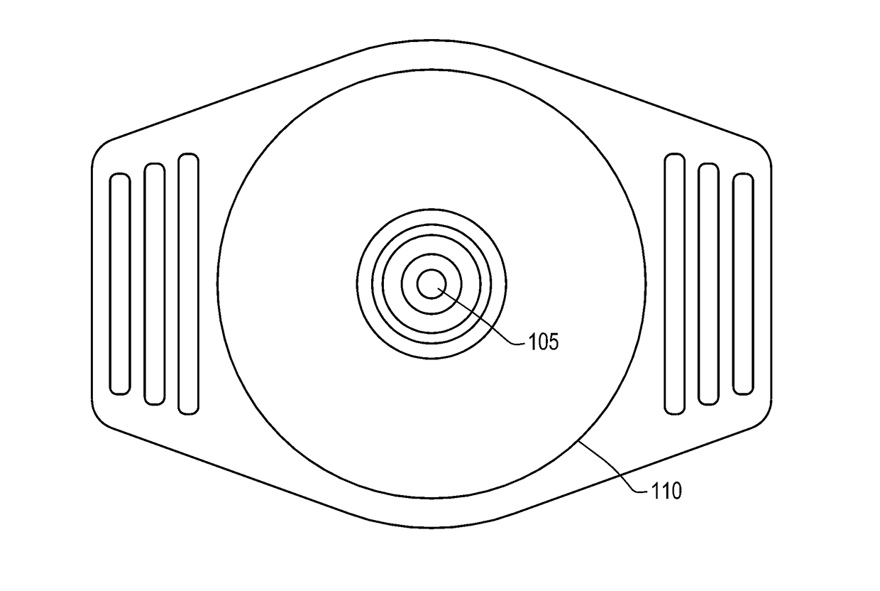
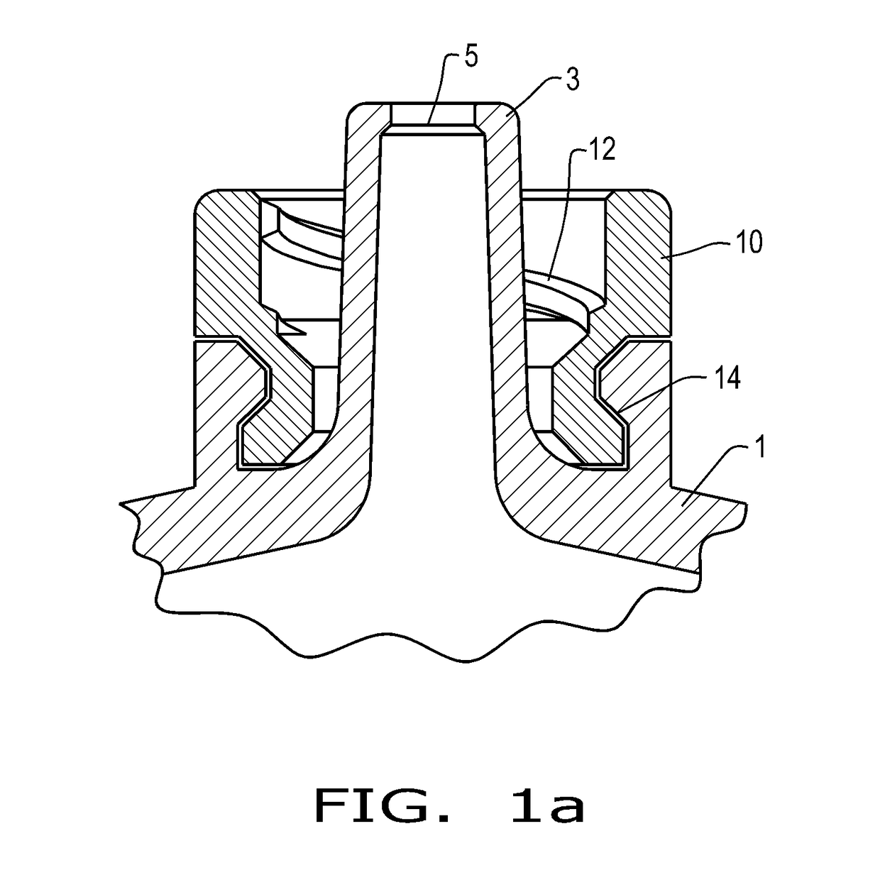
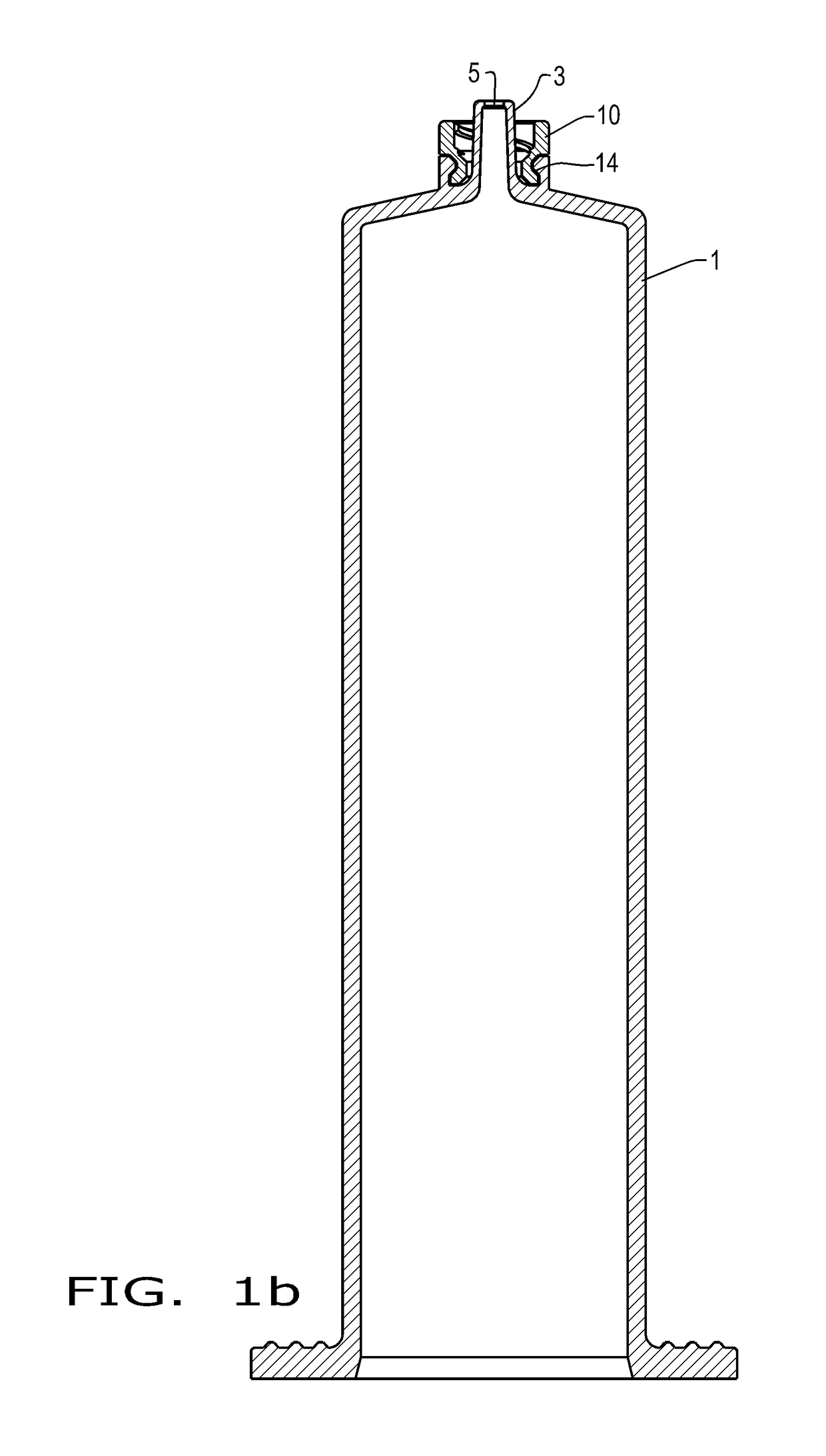
[0038]Referring now to the drawings, and more particularly to FIG. 1, there is shown a syringe body 1 which generally includes a syringe cone 3, with a distal opening 5. Of entire syringe body 1, only the upper part of the syringe in the region of syringe cone 3 is shown. Syringe body 1 preferably consists of a hard plastic, for example a cycloolefin-copolymer (COC) or cycloolefin-polymer (COP). A connector 10 for connectors or respectively attachment of syringes is arranged about syringe cone 3. Connection 10 in this example is an attachment with an inside thread 12, without being limited to same. Connection 10 in this example is an independent part vis-à-vis syringe body 3. In the illustrated embodiments according to FIG. 1, the syringe body as the first component and the connector as the second component are only mechanically connected with one another. For example, connection 10 is placed onto the syringe body and is locked in place in an undercut 14, in other words, the connect...


PUM

PropertyMeasurementUnit
temperatureaaaaaaaaaa
temperaturesaaaaaaaaaa
impact strengthaaaaaaaaaa

Abstract

A syringe includes a syringe body, a syringe cone having a distal opening, and a connection arranged in the region of the syringe cone, wherein the syringe body includes a first material and the connection includes a second material, and wherein the first material is different from the second material and the second material is a softer material than the first material.

Description

BACKGROUND OF THE INVENTION1. Field of the Invention[0001]The invention relates to syringes, and in particular, syringes having a syringe body, a syringe cone including a distal opening, and a connection arranged in the region of the syringe cone.2. Description of the Related Art[0002]Syringes have become known from a multitude of patents that have a connection for various connectors that are mounted manually onto the tip of the syringe.[0003]A syringe of this type is described, for example in US 2013 / 079 276 A. A syringe body has become known from US 2013 / 079 276 A wherein a transport cap, an intravenous port or an injection needle can be screwed into a thread above the syringe cone. If, for example a transport cap is screwed into the thread, the syringe cone can be protected.[0004]A syringe with a thread in the region of the Luer-Lock connection has become known from DE 202 158 07 U1, wherein the thread is part of the syringe body. The Luer-Lock connection according to DE 202 158 ...

Claims


Application Information

Patent Timeline
Patent Type & Authority Applications(United States)
IPC IPC(8): A61L31/04A61M5/34A61L31/06B29C65/56B29C65/08B29C65/00B29C45/00B29C45/16
CPCA61L31/048A61M5/346A61M5/347A61M5/345A61L31/06B29C65/565B29C65/08B29C66/73152B29C66/72B29C66/712B29C45/0001B29C45/164B29C45/1676A61M2207/00B29K2023/38B29K2023/06B29K2023/08B29K2023/12B29K2995/007B29K2995/0089B29L2031/7544A61M5/178A61M5/34A61M2205/02A61M5/3134A61M5/344
Inventor AUERBACH, JUDITHFISCHER, BASTIANDERKSEN, HELENA
Owner SCHOTT PHARMA AG & CO KGAA
Why Eureka
Try Eureka