
Turbofan case for controlling blade deflection

a technology of blade deflection and turbine case, which is applied in the direction of efficient propulsion technologies, machines/engines, liquid fuel engines, etc., can solve the problems of fan blade deflection, unstable blade deflection, and limited air that is able to bypass the fan through the gap

Active Publication Date: 2018-07-19
GENERAL ELECTRIC CO
View PDF0 Cites 10 Cited by
  • Summary
  • Abstract
  • Description
  • Claims
  • Application Information

AI Technical Summary

Benefits of technology

The present invention relates to a way to make a structure for containing a rotating blade in a turbofan engine. The structure has a cylindrical region made of abradable material which is placed in front of the rotating blades. This abradable material is designed to be worn down by the blades during operation. The invention also includes a method for measuring and determining the shape of the structure using a rub load condition and blade deflection measurements. This invention allows for a close tolerance between the rotating blades and the structure, which improves engine performance and durability.

Problems solved by technology

Conventionally, the radial gap is very narrow such that the amount of air that is able to bypass the fan through the gap is limited.
However, any rubbing contact between the tips of the fan blades and the shroud will tend to cause the fan blades to deflect and eventually become unstable.

Method used


Image

  • Turbofan case for controlling blade deflection
  • Turbofan case for controlling blade deflection
  • Turbofan case for controlling blade deflection

Examples


Embodiment Construction

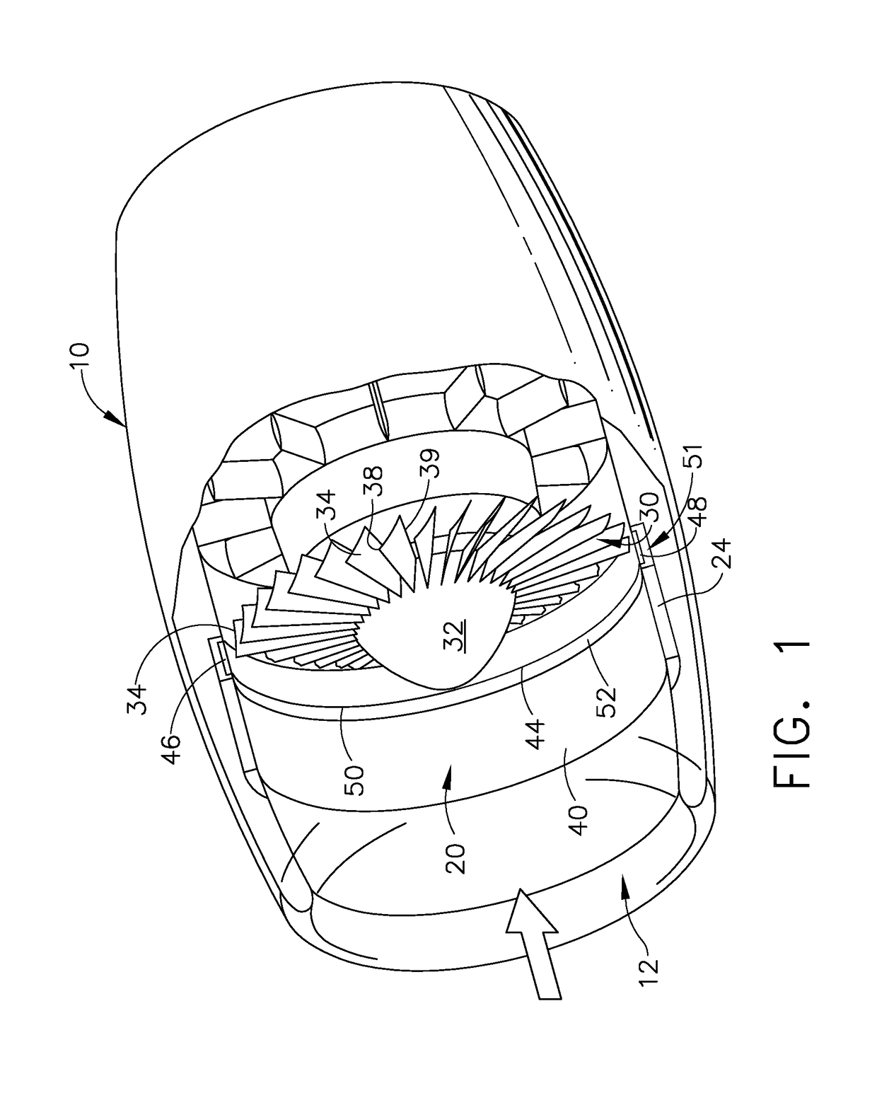
[0012]Referring to the drawings wherein identical reference numerals denote the same elements throughout the various views, FIG. 1 illustrates an abradable fan containment structure 20 for use in turbomachinery, such as a high bypass turbofan engine 10 shown in FIG. 1. The containment structure 20 can be used in other machinery that includes a rotation structure such as pumps, compressors, or turbomachinery. In the configuration shown, the engine 10 includes a rotation structure that is a fan 12 and a fan case 24. The fan 12 includes a plurality of fan blades 30. The fan blades 30 are mounted to a fan disk 32 which is located within the fan section 12 of the engine 10. In the configuration shown, the engine 10 includes a rotating structure that is a fan 12 and a plurality of fan blades 30. The fan blades 30 are mounted to the fan disk 32.

[0013]The fan blades 30 include blade tips 34 that define a circular path that has an outer diameter. The blades 30 are configured such that the bl...


PUM


Abstract

A containment structure configured to provide close tolerance for a rotation structure. The containment structure includes an annular inner casing having an inner annular surface being formed of an abradable material. The rotation structure is configured to be received within the annular inner casing such that the rotation structure is normally spaced-apart from the inner annular surface. The inner annular surface surrounds the rotation structure and has a first width. The rotation structure has a second width and the first width is greater than the second width. At least a section of the inner annular surface of the abradable material is cylindrical.

Description

BACKGROUND OF THE INVENTION[0001]The present invention relates to abradable shroud assemblies for use in turbomachinery, such as gas turbine engines. More particularly, this invention relates to a geometric profile of a containment case in regions forward of where a rotating blade row is aligned.[0002]In most turbofan engines the fan is contained by a fan case that is equipped with a shroud. The shroud circumscribes the fan and is adjacent to the tips of the fan blades. The shroud serves to channel incoming air through the fan so as to ensure that most of the air entering the engine will be compressed by the fan. A small portion of the air is able to bypass the fan blades through a radial gap present between the tips of the fan blades and the shroud. Conventionally, the radial gap is very narrow such that the amount of air that is able to bypass the fan through the gap is limited. The efficiency of the engine can be significantly improved in this way.[0003]Because the gap is narrow,...

Claims


Application Information

Patent Timeline
Patent Type & Authority Applications(United States)
IPC IPC(8): F04D29/52F02K3/06F04D19/00F04D25/04F04D29/32F04D29/38
CPCF04D29/526F02K3/06F04D19/002F04D25/045F05D2270/09F04D29/38F05D2220/323F05D2220/36F05D2260/35F04D29/329F01D11/122F01D11/127F01D21/045F04D29/547F05D2240/303F05D2250/231F05D2260/941Y02T50/60F05D2260/81G06G7/64G06F30/23
Inventor KRAY, NICHOLAS JOSEPH
Owner GENERAL ELECTRIC CO
Learn More