Shoulder Implant Components

a technology of shoulder implants and components, applied in shoulder joints, medical science, prosthesis, etc., to achieve the effect of providing rotational stability and rotational stability

Active Publication Date: 2018-07-19
ENCORE MEDICAL L P D B A DJO SURGICAL
View PDF0 Cites 12 Cited by
  • Summary
  • Abstract
  • Description
  • Claims
  • Application Information

AI Technical Summary

Benefits of technology

[0008]According to some implementations of the present disclosure, a humeral stem implant includes a lower stem portion, an upper stem portion, a first pair of fins, and a second pair of fins. The lower stem portion has a central axis. The upper stem portion extends from the lower stem portion and has a tapered face that is angled relative to the central axis of the lower stem portion. The first pair of fins extends from an exterior surface of the upper stem portion for providing rotational stability to the humeral stem implant by engaging cancellous bone. The second pair of fins extends from the exterior surface of the upper stem portion for providing rotational stability to the humeral stem implant by engaging cancellous bone. The second pair of fins is generally located on an opposite side of the upper stem portion relative to the first pair of fins.
[0009]According to some implementations of the present disclosure, a humeral stem implant includes a lower stem portion, an upper stem portion, a first pair of parallel fins, and a second pair of parallel fins. The lower stem portion has a central axis. The upper stem portion extends from the lower stem portion and has a tapered face that is angled relative to the central axis of the lower stem portion. The first pair of parallel fins is coupled to a posterior portion of an exterior surface of the upper stem portion. The second pair of parallel fins is coupled to an anterior portion of the exterior surface of the upper stem portion. The first pair of parallel fins and the second pair of parallel fins are configured to provide rotational stability to the humeral stem implant by directly engaging cancellous bone responsive to the humeral stem implant being seated in a humeral canal of a prepared humerus bone of a patient.
[0010]According to some implementations of the present disclosure, a humeral stem implant includes a lower stem portion, an upper stem portion, a first longitudinal fin, a second longitudinal fin, and a biologic ingrowth coating. The lower stem portion has a central axis. The upper stem portion extends from the lower stem portion and has a tapered face that is angled relative to the central axis of the lower stem portion. The first longitudinal fin has a first central axis and a first length and is coupled to a posterior portion of an exterior surface of the upper stem portion such that the first longitudinal fin forms a first window that is configured to receive a suture therethrough. The first longitudinal fin tapers inwardly such that the first central axis is at a first angle relative to the central axis of the lower stem portion. The second longitudinal fin has a second central axis and a second length and is coupled to the posterior portion of the exterior surface of the upper stem portion such that the second longitudinal fin forms a second window that is configured to receive a suture therethrough. The second longitudinal fin tapers inwardly such that the second central axis is at a second angle relative to the central axis of the lower stem portion. The second angle is different than the first angle. The second length is less than half of the first length. The first longitudinal fin and the second longitudinal fin are configured to provide rotational stability to the humeral stem implant by directly engaging cancellous bone responsive to the humeral stem implant being seated in a humeral canal of a prepared humerus bone of a patient. The biologic ingrowth coating is attached to a majority portion of the exterior surface of the upper stem portion such that the biologic ingrowth coating extends downward from the tapered face at least one millimeter beyond the first longitudinal fin.
[0016]According to some implementations of the present disclosure, a glenoid implant is provided that is to be coupled with a prepared glenoid of a patient. The prepared glenoid has a mating surface, a central bore, and a peripheral bore. The glenoid implant includes a body, a central peg, and a peripheral peg. The body has a concave surface configured to engage a humeral head implant component, and a convex surface configured to engage the mating surface of the prepared glenoid of the patient. The convex surface has a peripheral area surrounding a central area. The central peg extends from the central area of the convex surface. The central peg is configured to be affixed to the central bore of the prepared glenoid of the patient. The peripheral peg extends from the peripheral area of the convex surface. The peripheral peg has at least one radially extending feature. Responsive to at least a portion of the convex surface directly engaging the mating surface of the prepared glenoid, the at least one radially extending feature of the peripheral peg is configured to engage cancellous bone of the prepared glenoid and provide a sufficient amount of self-pressurization such that bone cement between the central peg and the central bore can cure with the at least a portion of the convex surface maintaining its direct engagement with the mating surface of the prepared glenoid without an external force being applied to the glenoid implant.

Problems solved by technology

Some prior stem implants have a relatively long body that enters into the diaphysis region of the humerus to aid in aligning the stem implant during installation and can thus end up engaging the cortical bone, which can be undesirable.

Method used


Image

  • Shoulder Implant Components
  • Shoulder Implant Components
  • Shoulder Implant Components

Examples


Embodiment Construction

[0054]While this disclosure is susceptible to embodiment in many different forms, there is shown in the drawings and will herein be described in detail preferred implementations of the disclosure with the understanding that the present disclosure is to be considered as an exemplification of the principles of the disclosure and is not intended to limit the broad aspect of the disclosure to the implementations illustrated.

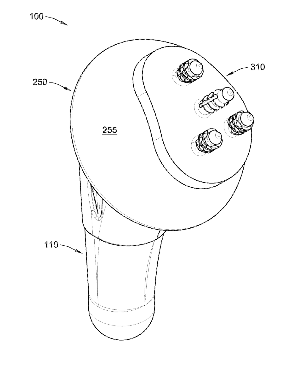
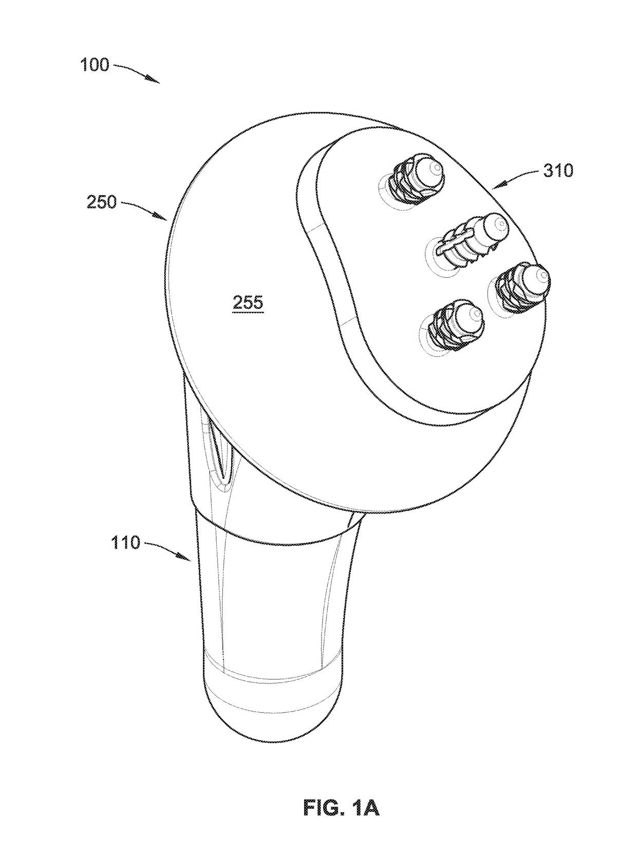
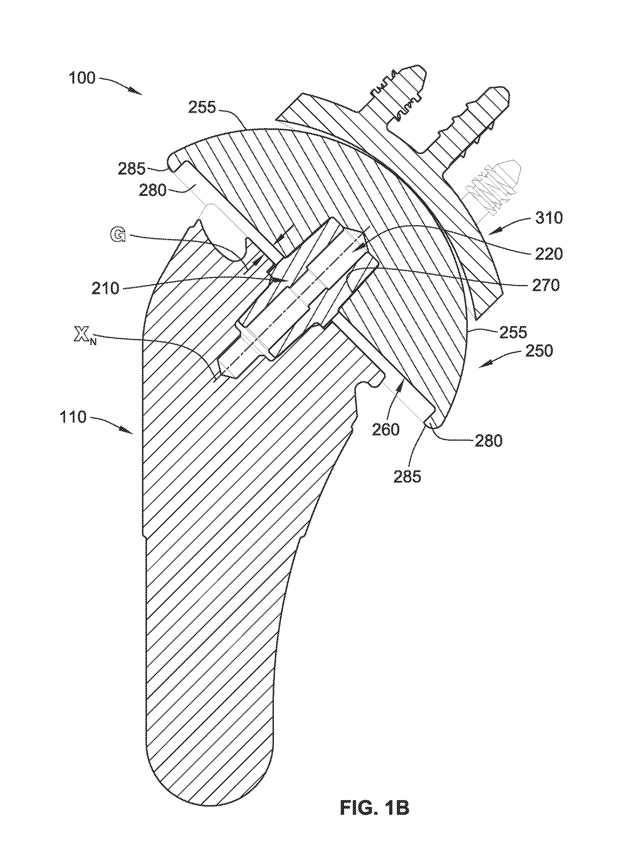
[0055]Referring generally to FIGS. 1A-2B, a shoulder implant system 100 includes a humeral stem implant 110, a humeral neck implant component 210, a humeral head implant component 250, and a glenoid implant 310. Generally, the humeral stem implant 110 is installed / implanted in a prepared humerus bone of a patient such that a portion (e.g., a tapered face 132 shown in FIG. 7A) of the humeral stem implant 110 remains exposed to be coupled with a first end portion 212a (FIGS. 2A and 2B) of the humeral neck implant component 210. As such, a second opposing end portion 21...


PUM


Abstract

A shoulder implant system includes a humeral stem implant, a humeral neck implant component, a humeral head implant component, and a glenoid implant. The humeral stem implant has a fin coupled to an exterior surface thereof that is inwardly tapered at an angle relative to vertical. At least a portion of the fin forms a wedge that directly engages and compacts cancellous bone during installation of the humeral stem implant. The humeral neck implant component is configured to be coupled with the humeral stem implant. The humeral head implant component is configured to be coupled to the humeral stem implant via the humeral neck implant component. The glenoid implant has a plurality of peripheral pegs. Each of the peripheral pegs has a plurality of sets of resilient lobes.

Description

CROSS-REFERENCE TO RELATED APPLICATIONS[0001]This application claims the benefit of and priority to U.S. Provisional Application No. 62 / 448,205, filed Jan. 19, 2017, which is hereby incorporated by reference herein in its entirety.COPYRIGHT[0002]A portion of the disclosure of this patent document contains material which is subject to copyright protection. The copyright owner has no objection to the facsimile reproduction by anyone of the patent disclosure, as it appears in the Patent and Trademark Office patent files or records, but otherwise reserves all copyright rights whatsoever.FIELD OF THE INVENTION[0003]The present disclosure relates generally to shoulder implant systems and, more particularly, to a shoulder implant systems with a humeral stem implant and a glenoid implant.BACKGROUND[0004]People experiencing shoulder joint pain can find relief by way of a shoulder replacement surgery that replaces one or more portions of the person's anatomy with one or more implant component...

Claims


Application Information

Patent Timeline
Patent Type & Authority Applications(United States)
IPC IPC(8): A61F2/40
CPCA61F2/4014A61F2/4081A61F2/4059A61F2002/30884A61F2/4612A61F2002/4029A61F2002/4037A61F2002/4044A61F2002/30405A61F2002/30331A61F2002/30171A61F2002/30822A61F2002/30878A61F2002/30881A61F2002/30892A61F2002/30897A61F2002/4062A61F2002/30851
Inventor AXELSON, JR., STUART L.DICKSON, ANDREW M.WIDDING, KIRSTINABBOUD, JOSEPH ALBERTNAMDARI, SURENAFRANKLE, MARK ALANLEVY, JONATHAN C.WILLIAMS, JR., GERALD ROSSPLOWMAN, NATHAN OLIVERHYER, RICHARD JUSTIN
Owner ENCORE MEDICAL L P D B A DJO SURGICAL
Why Eureka
Try Eureka