Ultrasonic Catheter Assembly

a catheter and ultrasonic technology, applied in the field of medical catheters, can solve the problems of catheter damage, catheter tip being moved away from the target zone, catheter cannot be steered to the target zone, etc., and achieve the effect of enhancing ultrasonic imaging of the catheter

Pending Publication Date: 2018-07-19
AVENT INC
View PDF2 Cites 9 Cited by
  • Summary
  • Abstract
  • Description
  • Claims
  • Application Information

AI Technical Summary

Benefits of technology

[0018]In yet another aspect, the present disclosure is directed to a method of manufacturing an active ultrasonic assembly. The method includes providing a catheter having a side wall that extends from a proximal end to a distal end. The side wall of the catheter defines an inner surface that forms a lumen extending from the proximal end to the distal end. Thus, the lumen is configured to deliver a treatment fluid from the proximal end to the distal end. The method also includes securing one or more piezoelectric components with the distal end of the catheter. Thus, the piezoelectric component(s) are configured to enhance ultrasonic imaging of the catheter.

Problems solved by technology

One problem with this approach is that catheter insertion through the needle may move the tip of the needle away from the target zone.
The problem with this is that the catheter cannot be steered to the target zone without risking pulling back through the needle and potentially damaging the catheter.
In addition, the additional time needed to place and maneuver the catheter is significant and after the catheter is secured, it can dislodge by patient movement and become ineffective.
Ultrasound guided techniques have added imaging to such procedures, but they are mainly used to see the adjacent vessels and are not always good at seeing the needle and / or catheter.
The problem with ultrasound guided techniques is that the catheter cannot be easily seen through tissue.
That is, the ability to see the tip and / or other portions of the catheter under ultrasound imaging techniques is limited.
Another problem is that conventional catheters do not allow one to place the catheter quickly allowing for some small migration or tip mis-positioning while still delivering drug to the target area.

Method used


Image

  • Ultrasonic Catheter Assembly
  • Ultrasonic Catheter Assembly
  • Ultrasonic Catheter Assembly

Examples


Embodiment Construction

[0047]Reference will now be made in detail to one or more embodiments of the invention, examples of the invention, examples of which are illustrated in the drawings. Each example and embodiment is provided by way of explanation of the invention, and is not meant as a limitation of the invention. For example, features illustrated or described as part of one embodiment may be used with another embodiment to yield still a further embodiment. It is intended that the invention include these and other modifications and variations as coming within the scope and spirit of the invention.

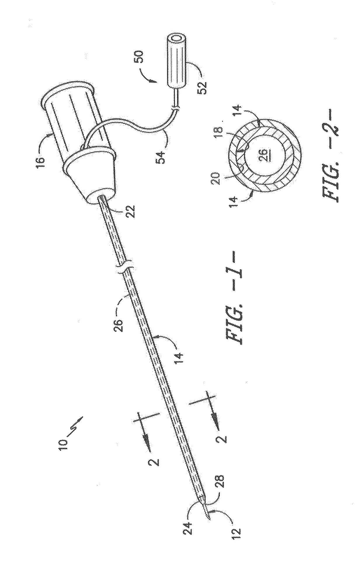
[0048]The positional terms “proximal” and “distal” are used herein to orient the various components relative to each other and to the patient. “Distal” refers to the direction that is closest to the wound site (e.g., the distal end of the connector is the end oriented towards a catheter insertion site), and “proximal” refers to the opposite direction (e.g., the proximal end of the catheter is inserted into th...


PUM


Abstract

The present disclosure is directed to an ultrasonic catheter assembly. More specifically, the catheter assembly includes a catheter and one or more piezoelectric or echogenic components. The catheter has a side wall that extends from a proximal end and a distal end that defines a lumen extending from the proximal end to the distal end. Thus, the lumen is configured to deliver a treatment fluid from the proximal end to the distal end. In addition, the piezoelectric component(s) are configured with the side wall of the catheter and/or embedded at least partially within the side wall of the catheter. As such, the piezoelectric component(s) are configured to enhance ultrasonic imaging of the catheter, e.g. when activated by a stimulator assembly.

Description

RELATED APPLICATIONS[0001]The present application claims priority to International Application Number PCT / US2015 / 041242 filed on Jul. 21, 2015, which is incorporated herein in its entirety by reference hereto.FIELD OF THE INVENTION[0002]The present invention relates generally to the field of medical catheters and more particularly to a catheter assembly configured to provide enhanced ultrasonic imaging.BACKGROUND[0003]Prior to performing a surgical operation on a part of the body, it may be desirable to perform a nerve block in order to anesthetize a nerve bundle in a part of the body proximate to where surgery will occur. Often, a catheter-based infusion system is utilized to both block the nerve bundle for surgery and to provide a continuous, low flow rate of the anesthetic over a period of time (e.g., 2-3 days following surgery) for post-operative pain management.[0004]One approach is to introduce an epidural-type needle or needle and peel-away-type sheath into the general area o...

Claims


Application Information

Patent Timeline
Patent Type & Authority Applications(United States)
IPC IPC(8): A61B8/00A61B8/12A61B8/08
CPCA61B8/445A61B8/12A61B8/0833A61B5/06A61B8/0841
Inventor COKER, JUSTIN JEFFREYHSU, KENNETH C.JUN, PAULKHALAJ, STEVE S.
Owner AVENT INC
Why Eureka
Try Eureka