
Vertical displacement detecting device

a detection device and vertical technology, applied in the field of displacement detection, can solve the problems of complicated displacement detection devices, low detection accuracy, and low cost of their own cost, and achieve the effects of easy breakage, good toughness, and good toughness

Active Publication Date: 2018-07-12
GUANGXI GEOTECHNICAL NEW TECH CO LTD
View PDF3 Cites 5 Cited by
  • Summary
  • Abstract
  • Description
  • Claims
  • Application Information

AI Technical Summary

Benefits of technology

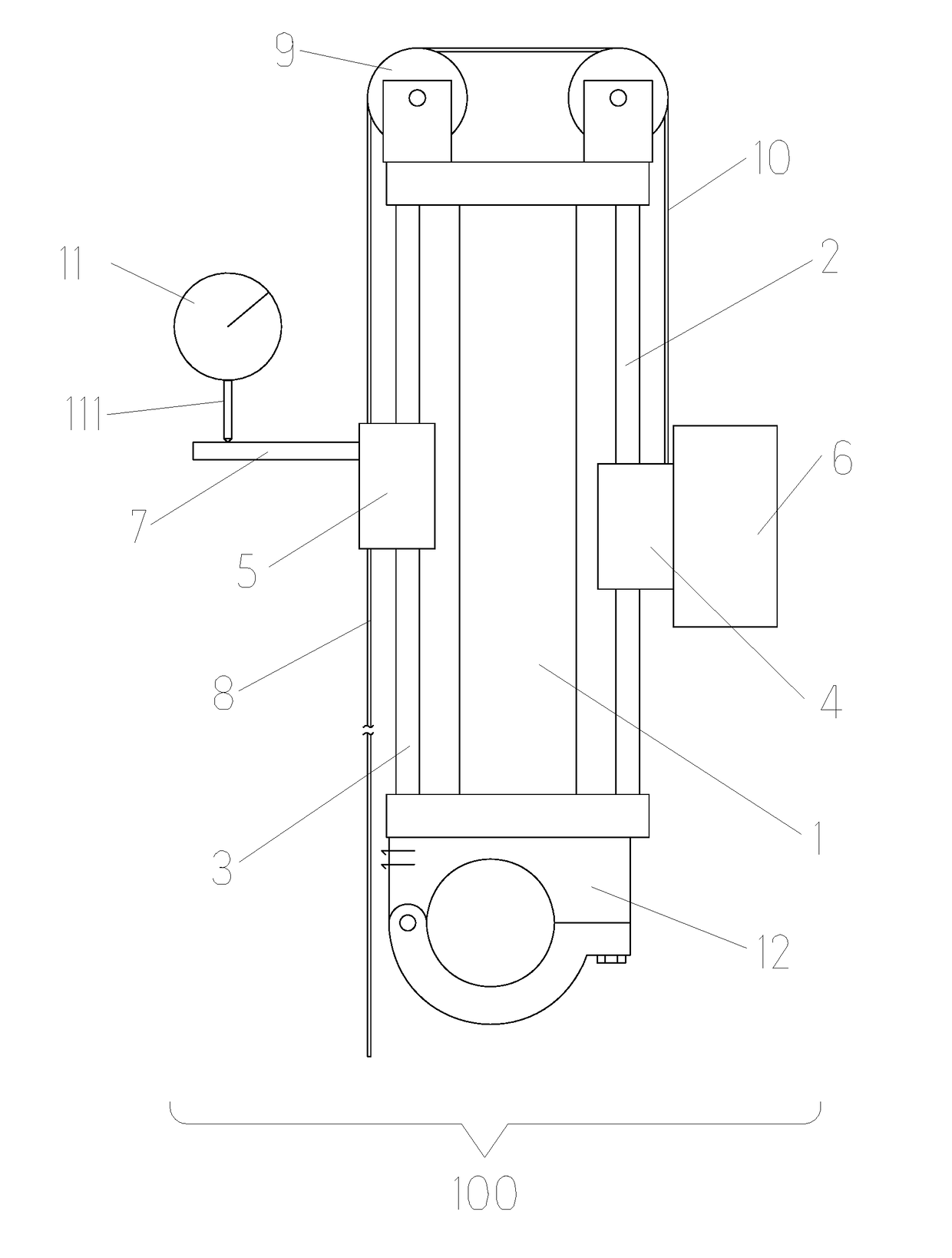
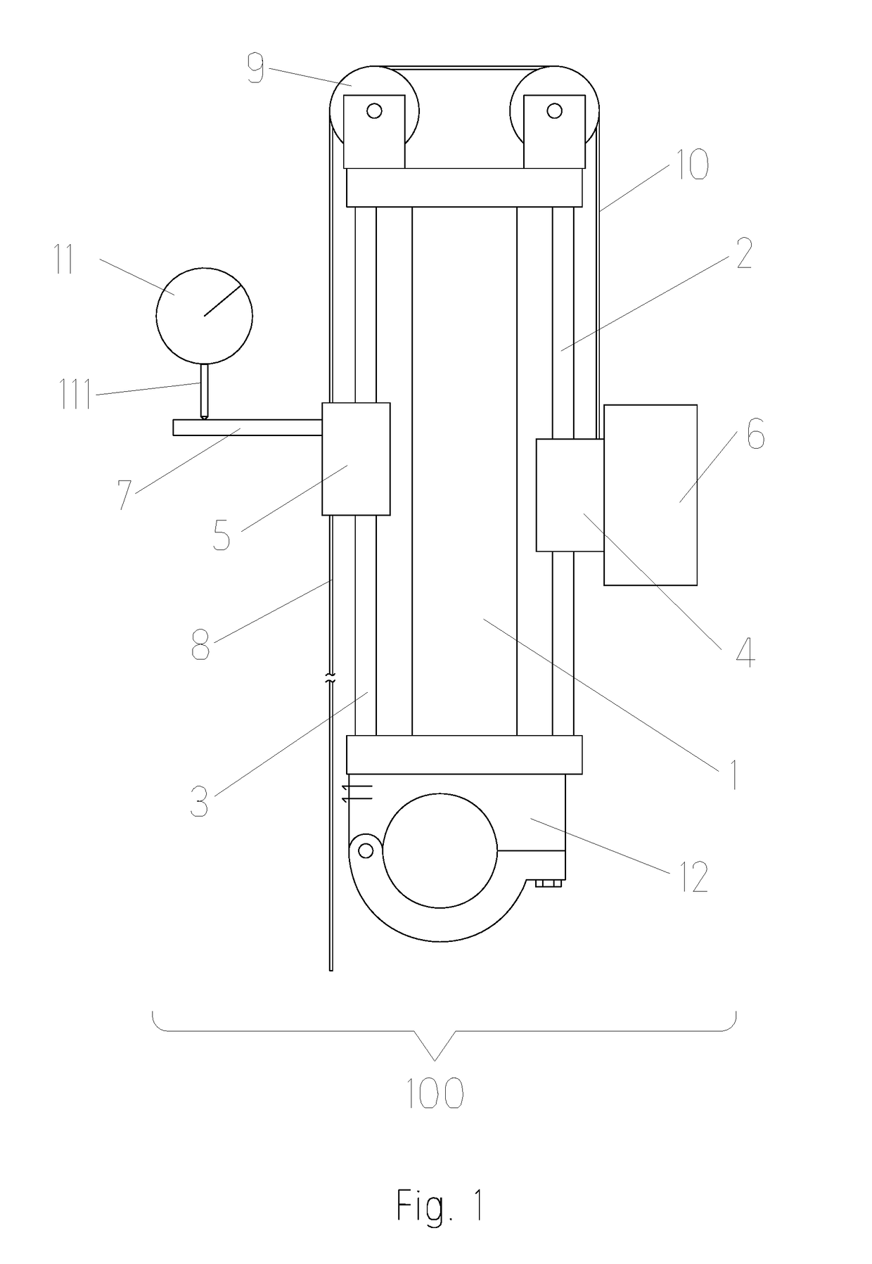
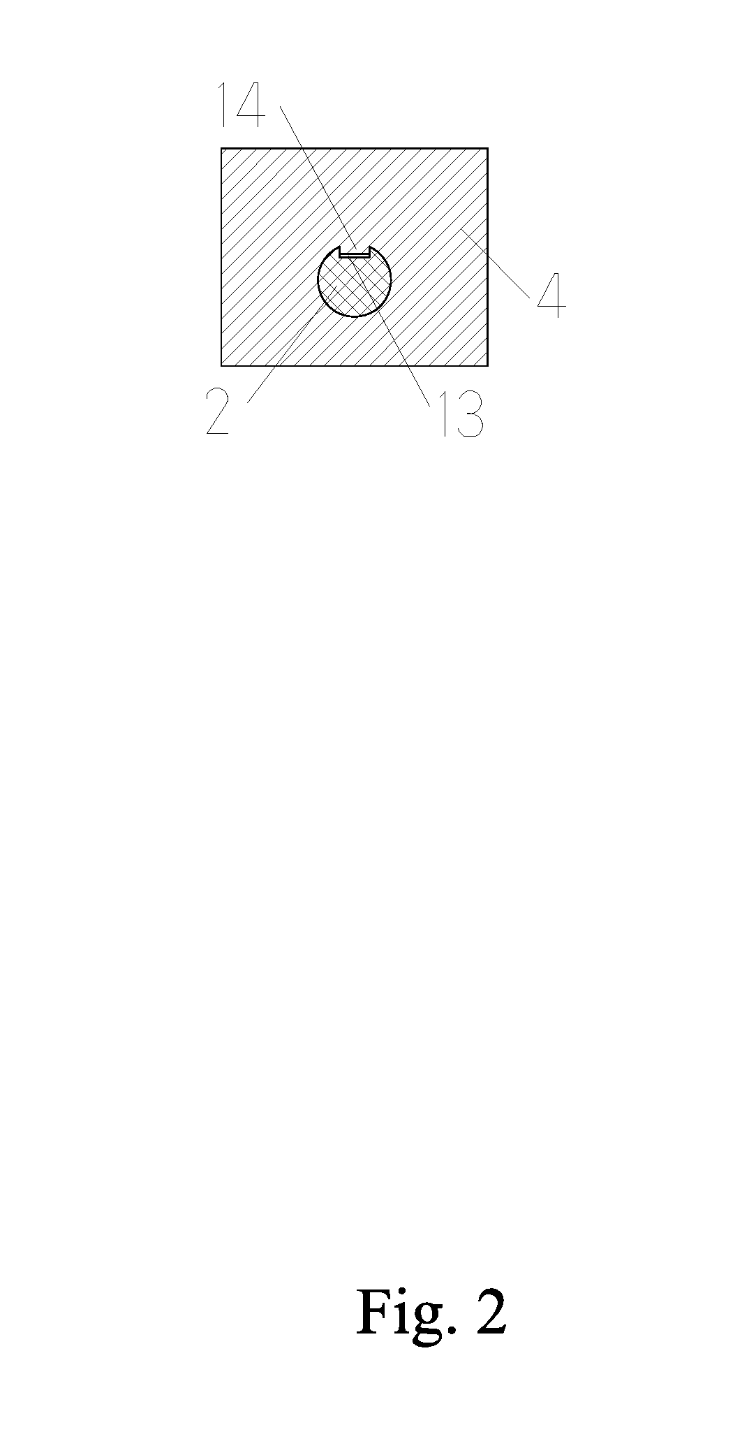
The present disclosure provides a vertical displacement detecting device with a simple structure and accurate measurement. The device uses a dial gage or displacement sensor, like a sliding block and anti-rotating bumps on guiding rails to prevent rotation. The traction wire, either a steel wire rope or iron wire, is strong and less prone to deformation. A pulling part and gravity action are used to temporarily stationary the second sliding block and object to be detected, and the displacement wire moves to measure the vertical displacement of the object. The disclosure has the advantages of simple structure, accurate precision, low cost, and wide use.

Problems solved by technology

However, the domestic self-balancing method often uses the method of connecting the displacement rod on the upper and lower surfaces of the load box to measure the displacement of the pile, which in some cases is not accurate and its own cost is relatively expensive, so the method is not widely used.
In the prior art, the displacement detecting device is complicated and the method is relatively cumbersome.
Like laser measurement, it is possible to achieve a more accurate measurement of the displacement, but the supporting facilities are expensive, and it is difficult to be used in multiple spot and large scale, and the application is restricted greatly.

Method used


Image

  • Vertical displacement detecting device
  • Vertical displacement detecting device
  • Vertical displacement detecting device

Examples


Embodiment Construction

[0019]In the following, the technical solutions in the embodiments of the disclosure will be described with reference to the accompanying drawings in the embodiments of the disclosure. Obviously, the described embodiments are merely part of the present disclosure, and not the whole. All other embodiments obtained by those of ordinary skill in the art without making creative work based on embodiments in the present disclosure are within the scope of the present disclosure.

[0020]Referring to FIGS. 1, 2 and 3, the present disclosure provides a vertical displacement detecting device. A vertical displacement detecting device 100 comprises a fixed frame 1 and a first guiding rail 2 and a second guiding rail 3 provided on both sides of the fixed frame 1 respectively, the first guiding rail 2 and the second guiding rail 3 are provided with a first sliding block 4 and a second sliding block 5 respectively, the first sliding block 4 is provided with a pulling part 6, and the second sliding bl...


PUM


Abstract

The disclosure relates to a vertical displacement detecting device, comprising a fixed frame, a first guiding rail and a second guiding rail. The first guiding rail and the second guiding rail are respectively provided with a first sliding block and a second sliding block. The top or bottom surface of the blocking plate is contacted with a displacement detector. The second sliding block is provided with a traction wire. A top end of the fixed frame is provided with a pulley and a traction wire, and the traction wire is wound around the pulley, one end of the traction wire is connected with the first sliding block and the other end is connected to the second sliding block. The disclosure has the advantages of simple structure, accurate precision, low cost and simple realization method, and it is advantageous for wide use.

Description

FIELD OF THE INVENTION[0001]The present disclosure relates to the field of displacement detection, and more specifically, to a vertical displacement detecting device.BACKGROUND OF THE INVENTION[0002]In the field of production and engineering, the displacement of components and devices are usually measured to characterize the characteristics of components or devices by change of the displacement or to deduce the characteristics of components or devices by combining the displacement. For example, according to the requirements on the Code for Acceptance of Construction Quality of Building Foundation in China, static load detection of bearing capacity of foundation test pile and engineering pile should be performed to determine and test the bearing capacity of single pile, which is regarded as a mandatory article for the acceptance of pile quality requirements. Now the self-balancing method is commonly used in testing the bearing characteristics of the pile foundation. The self-balancin...

Claims


Application Information

Patent Timeline
Patent Type & Authority Applications(United States)
IPC IPC(8): G01M5/00
CPCG01M5/0058E02D33/00E02D2600/10F16H55/36G01B3/22G01B5/0004G01B5/0009
Inventor OU, XIAODUOLIN, CHUNCAIHOU, KAIWENJIANG, JIEZHAO, WANJINHOU, FUCHANGCHEN, JIANWEN
Owner GUANGXI GEOTECHNICAL NEW TECH CO LTD
Learn More