2D SCANNING HIGH PRECISION LiDAR USING COMBINATION OF ROTATING CONCAVE MIRROR AND BEAM STEERING DEVICES

a concave mirror and beam steering technology, applied in the field of light detection and ranging (lidar), can solve the problems of difficult to distinguish the pulse of light reflected by objects at a longer distance (e.g., 100 meters) from background noise signals, the typical lidar system may be bulky and expensive, and the system may not be readily/or prohibitively expensive to be integrated with a vehicl

Active Publication Date: 2018-07-05
INNOVUSION INC
View PDF7 Cites 146 Cited by
  • Summary
  • Abstract
  • Description
  • Claims
  • Application Information

AI Technical Summary

Benefits of technology

The patent describes a system that uses light to detect and measure objects. It consists of a laser that emits light pulses and a device that directs the laser in different directions to illuminate objects. The system also collects the reflected light from the objects and redirects it to detectors. The main technical effect of this system is that it enables precise and accurate ranging of objects, making it useful in various fields such as autonomous vehicles.

Problems solved by technology

However, these on-chip MEMS designs typically yield an optical aperture cross-section that is a few (less than 5) millimeters or less, which makes it difficult to distinguish a pulse of light reflected by objects at longer distance (e.g., 100 meters) from background noise signals.
However, a typical LiDAR system may be bulky and expensive due to its system configurations.
These systems may not be readily integrated with a vehicle and / or may be prohibitively costly to be integrated with a vehicle.
Some of the challenges for a high-precision LiDAR system is to reduce the size of LiDAR systems while increasing the cross-section collection optical aperture.

Method used


Image

  • 2D SCANNING HIGH PRECISION LiDAR USING COMBINATION OF ROTATING CONCAVE MIRROR AND BEAM STEERING DEVICES
  • 2D SCANNING HIGH PRECISION LiDAR USING COMBINATION OF ROTATING CONCAVE MIRROR AND BEAM STEERING DEVICES
  • 2D SCANNING HIGH PRECISION LiDAR USING COMBINATION OF ROTATING CONCAVE MIRROR AND BEAM STEERING DEVICES

Examples


Embodiment Construction

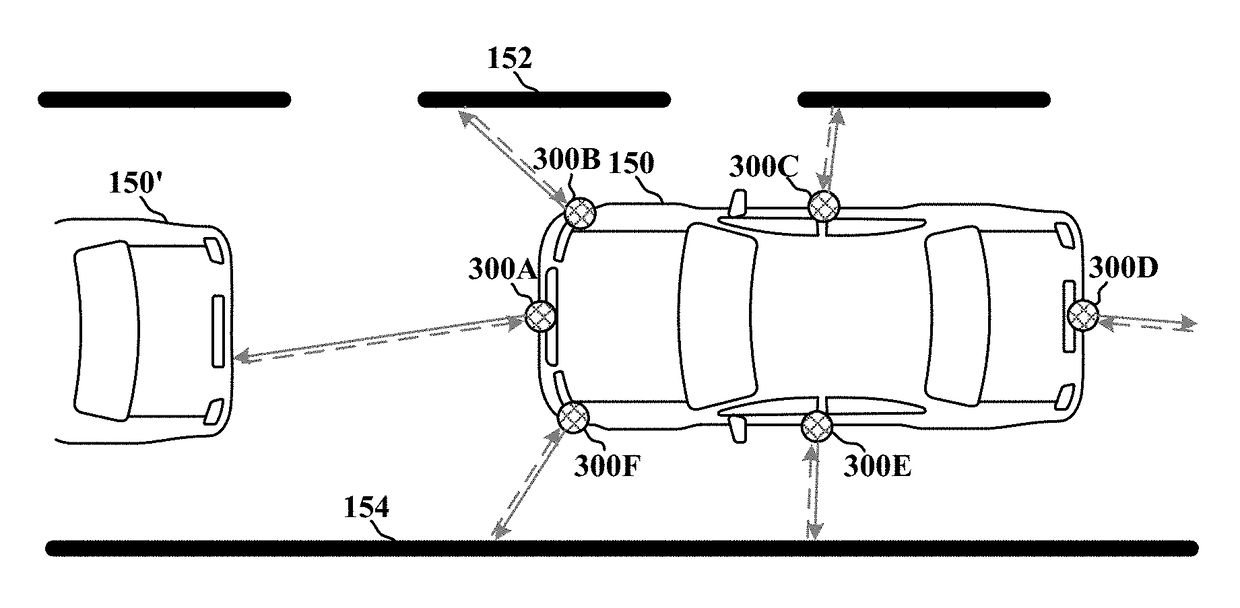
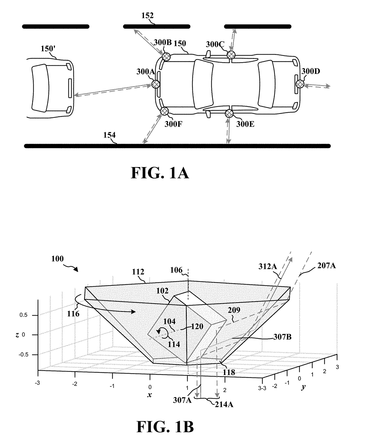
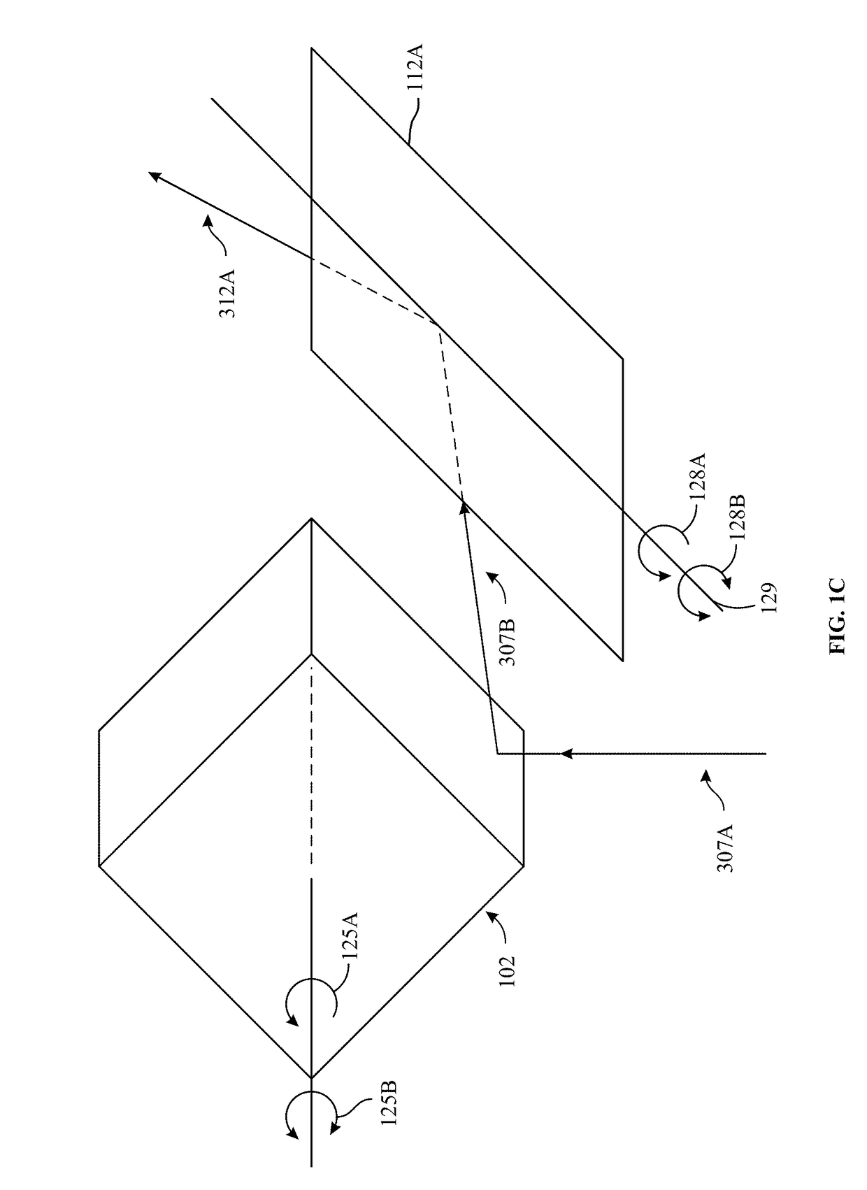
[0031]The detailed description set forth below in connection with the appended drawings is intended as a description of various configurations and is not intended to represent the only configurations in which the concepts described herein may be practiced. The detailed description includes specific details for the purpose of providing a thorough understanding of various concepts. However, it will be apparent to those skilled in the art that these concepts may be practiced without these specific details. In some instances, well-known structures and components are shown in block diagram form in order to avoid obscuring such concepts.

[0032]Examples of LiDAR scanning systems will now be presented with reference to various elements of apparatus and methods. These apparatus and methods will be described in the following detailed description and illustrated in the accompanying drawing by various blocks, components, circuits, steps, processes, algorithms, etc. (collectively referred to as “...


PUM


Abstract

The present disclosure describes a system and method for coaxial LiDAR scanning. The system includes a first light source configured to provide first light pulses. The system also includes one or more beam steering apparatuses optically coupled to the first light source. Each beam steering apparatus comprises a rotatable concave reflector and a light beam steering device disposed at least partially within the rotatable concave reflector. The combination of the light beam steering device and the rotatable concave reflector, when moving with respect to each other, steers the one or more first light pulses both vertically and horizontally to illuminate an object within a field-of-view; obtain one or more first returning light pulses, the one or more first returning light pulses being generated based on the steered first light pulses illuminating an object within the field-of-view, and redirects the one or more first returning light pulses.

Description

CROSS-REFERENCE TO RELATED APPLICATIONS[0001]This application claims priority to U.S. provisional patent application No. 62 / 441,280, entitled “COAXIAL INTERLACED RASTER SCANNING SYSTEM FOR LiDAR,” filed on Dec. 31, 2016; and U.S. provisional patent application No. 62 / 529,955, entitled “2D SCANNING HIGH PRECISION LiDAR USING COMBINATION OF ROTATING CONCAVE MIRROR AND BEAM STEERING DEVICES,” filed on Jul. 7, 2017. The content of both applications is hereby incorporated by reference (and appended hereto) in its entirety for all purposes.FIELD OF THE DISCLOSURE[0002]The present disclosure generally relates to a light detection and ranging (LiDAR) and, more specifically, to system for scanning consecutive light pulses to illuminate objects in a field-of-view and coaxially collecting the scattered light from each light pulse for ranging the objects in the field-of-view.BACKGROUND OF THE DISCLOSURE[0003]In order to reduce the size of LiDAR systems there is an effort to implement on-chip mi...

Claims


Application Information

Patent Timeline
Patent Type & Authority Applications(United States)
IPC IPC(8): G01S7/481G01S17/88G02B19/00G01S17/10G01S17/931
CPCG01S7/4812G01S7/4816G01S17/88G02B19/0076G01S17/10G01S7/4817G02B19/0028G01S17/931G01S7/481G01S7/4865G02B26/12G02B26/124G02B26/125G02B26/126G01S17/42G01S7/4814
Inventor BAO, JUNWEILI, YIMINZHANG, RUI
Owner INNOVUSION INC
Why Eureka
Try Eureka