
Method of automatically correcting projection area based on image photographed by photographing device and system therefor

Active Publication Date: 2018-06-21
CJ 4DPLEX CO LTD
View PDF1 Cites 4 Cited by
  • Summary
  • Abstract
  • Description
  • Claims
  • Application Information

AI Technical Summary

Benefits of technology

The present invention is about a method for automatically correcting high-quality corrections in a large-scale theater using a single photographing device. This method can effectively remove obstacles caused by the theater's structure and improve the accuracy of projecting onto multiple surfaces. Additionally, the use of a laser level can accurately correct the projection area. Overall, this invention enables better visual quality in theater settings.

Problems solved by technology

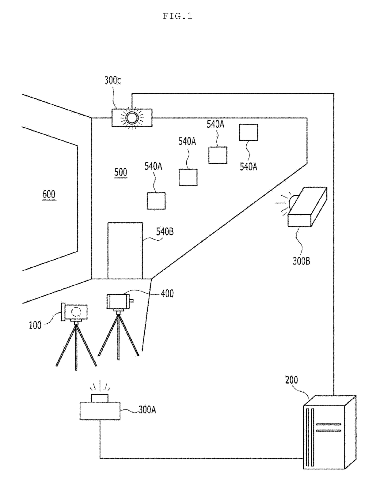
The cases of misplaced projectors are frequent in a theater due to vibration of an air conditioning system, an audio system or the like, and when the projectors are misplaced like this, contents such as a movie, an advertisement material or the like may not be projected at a correct location on a projection surface such as a screen or a wall, and thus the audience may not be provided with a proper motion picture projection service.

Method used


Image

  • Method of automatically correcting projection area based on image photographed by photographing device and system therefor
  • Method of automatically correcting projection area based on image photographed by photographing device and system therefor
  • Method of automatically correcting projection area based on image photographed by photographing device and system therefor

Examples


Embodiment Construction

[0034]Details of the objects and technical configuration of the present invention and operational effects according thereto will be clearly understood hereinafter by the detailed description based on the accompanying drawings attached in the specification of the present invention. Embodiments according to the present invention will be described in detail with reference to accompanying drawings.

[0035]In the following description, functional blocks shown in the figures and described below are merely examples of possible implementations. Accordingly, other functional blocks may be used in other implementations without departing from the spirit and scope of the detailed description. In addition, although one or more functional blocks of the present invention are expressed as individual blocks, one or more of the functional blocks of the present invention may be a combination of various hardware and software executing the same function.

[0036]In addition, the expression of ‘including’ an ...


PUM


Abstract

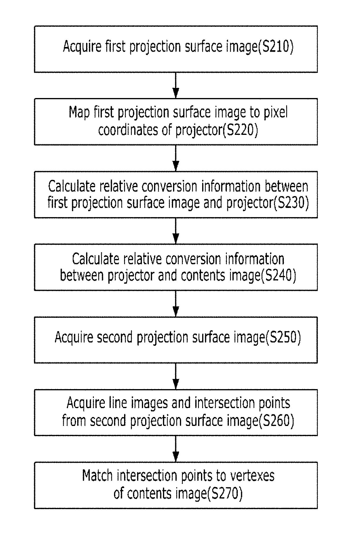
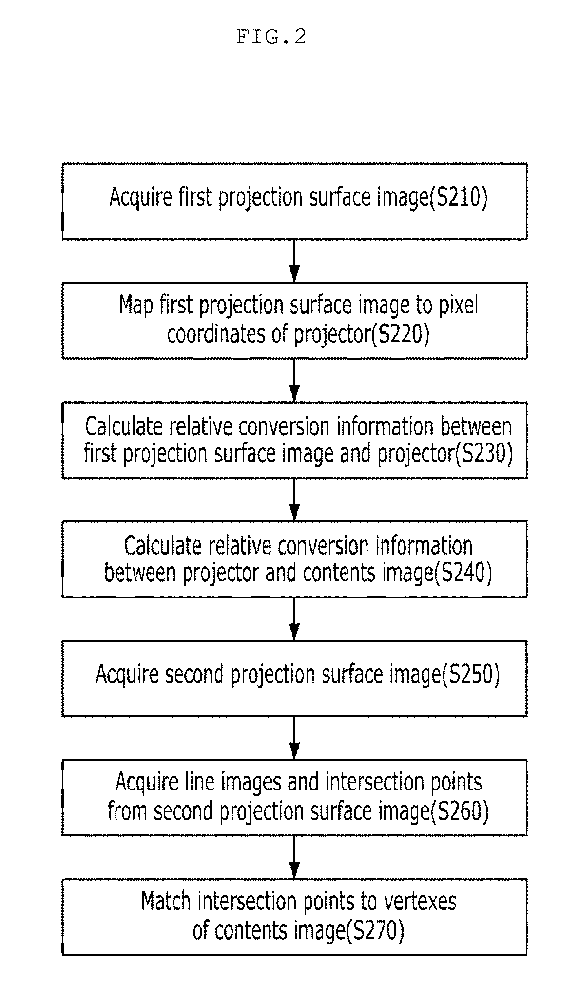
The present invention relates to automatic correction of an area on which contents are projected by a projector, i.e., a so-called projection area, in a theater, and specifically, to a method and system for automatically correcting a projection area by photographing a projection area in the theater using a photographing device such as a camera or the like, and matching the image photographed like this, coordinates of a projection area projected by the projector and finally a contents image projected on a projection surface such as a screen, a wall or the like so that eventually the contents image may be properly output in an effective projection area of a projection surface in the theater.

Description

CROSS REFERENCE TO RELATED APPLICATION[0001]The present application claims the benefit of Korean Patent Application No. 10-2016-0172309 filed in the Korean Intellectual Property Office on Dec. 16, 2016, the entire contents of which are incorporated herein by reference.TECHNICAL FIELD[0002]The present invention relates to automatic correction of an area on which contents are projected by a projector, i.e., a so-called projection area, in a theater, and specifically, to a method and system for automatically correcting a projection area by photographing a projection area in the theater using a photographing device such as a camera or the like, and matching the image photographed like this, coordinates of a projection area projected by the projector and finally a contents image projected on a projection surface such as a screen, a wall or the like so that eventually the contents image may be properly output in an effective projection area of a projection surface in the theater.BACKGROUN...

Claims


Application Information

Patent Timeline
IPC IPC(8): H04N9/31G06K9/46G06K9/62
CPCH04N9/3185G06K9/6201G06K9/46H04N9/3194H04N9/3191H04N9/3147G06T7/80G06T7/70H04N9/3176G06F18/22
Inventor JANG, KYUNG YOONYOON, HYUNG JIN
Owner CJ 4DPLEX CO LTD
Learn More