Universal electronic exchanger system for eyepieces, especially for telescopes

Active Publication Date: 2018-06-21
MARTINEZ MORALES ALVARO +1
View PDF0 Cites 1 Cited by
  • Summary
  • Abstract
  • Description
  • Claims
  • Application Information

AI Technical Summary

Benefits of technology

The present invention provides a universal electronic exchange system for telescopes that overcomes the drawbacks of prior art without requiring direct handling of the telescope. The system includes a revolver-type rotary plate for positioning and aligning tubular members with the optical axis, an electric motor for rotating the revolver-type rotary plate, and optical filters that prevent ambient light from entering the interface formed by the eyepices. The invention ensures an adequate optical performance regardless of atmospheric conditions, while solving the problems associated with prior art.

Problems solved by technology

The problem for amateur astronomers with an economical tripod or mount is changing the eyepieces or lenses of different magnifications.
In touching the telescope to extract an eyepiece and insert the next one with a higher or lower magnification, the telescope can sway or move (work is done in the dark) and this can cause the loss of the object being observed or photographed through the telescope.
However, the amateur astronomer tends to be reticent about spending money on a new tripod or mount when just starting out with their new hobby, as they would rather invest in other accessory equipment such as cameras, automatic colour filter changers, or other equipment.
However, this device does not resolve the fact of having to manually activate the change of eyepieces, and moreover does not include a universal support for image equipment, or a focus compensation system after changing the eyepiece.
Additionally, another typical problem for the market segment of advanced users with remote telescopes (expert amateurs, schools and universities) remotely controlled by a computer and located in areas of difficult access such as mountains or away from the cities, is the impossibility of changing the eyepiece when atmospheric conditions require it (the worse the “seeing” or atmospheric conditions, the lower the magnifications the eyepieces require): and as there are no automatic eyepiece exchangers, these telescopes work with their primary focus without an eyepiece or with a fixed eyepiece, making it impossible to decrease or increase the power according to atmospheric conditions, and diminishing their optical performance.
The above mentioned problems also occur when, instead of eyepieces or lenses, other kinds of optical devices are needed to be changed.

Method used


Image

  • Universal electronic exchanger system for eyepieces, especially for telescopes
  • Universal electronic exchanger system for eyepieces, especially for telescopes
  • Universal electronic exchanger system for eyepieces, especially for telescopes

Examples


first embodiment

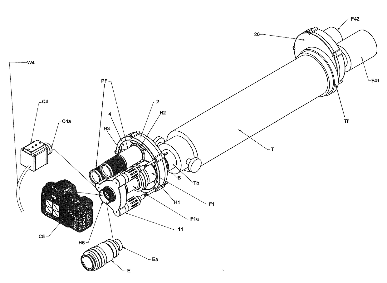
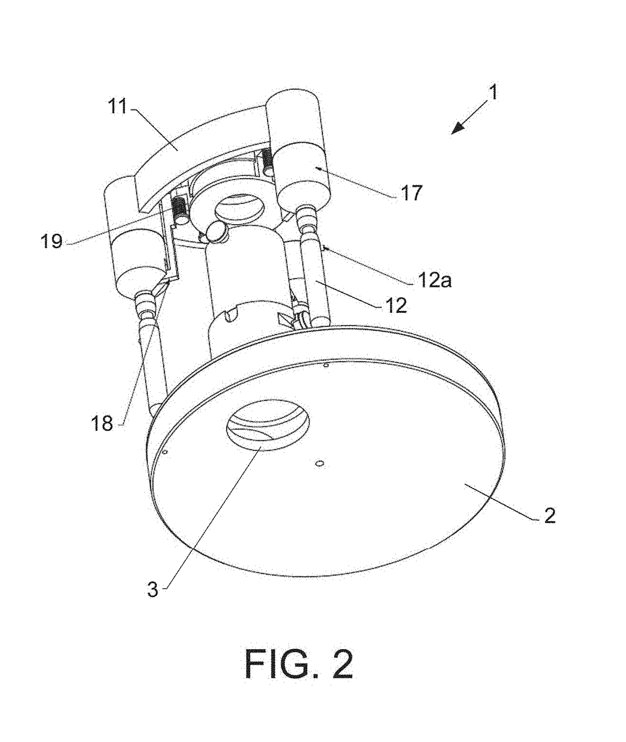
[0153] shown in FIGS. 1, 2 and 8 to 11, the actuation means of the movable shutter element 16 comprise a set of solenoids 17 coupled to the upper mounting plate 11 in respective housings 11 a and mounted with their respective axes 17a substantially parallel to the optical axis. It also comprises connection means, preferably pins 18, for transmission of the movement from the axes 17a of the solenoids 17 to the movable shutter element 16 in such a way that when the solenoids 17 are electrically activated said movable shutter element 16 is displaced towards the eyepiece in use until they couple together.

[0154]In reference to FIG. 11, each solenoid 17 includes a thread 17b coupled to a complementary thread 11b of the housing 11a of the upper mounting plate 11 (see FIG. 8) and a groove 17c made in said body of the solenoid 17 provided for passage of the end of the respective pin 18, each pin 18 being provided in turn at their end with an orifice 18a for coupling with the axis of the sole...

second embodiment

[0157] shown in FIGS. 12 to 17, the actuation means of the movable shutter element 16 comprise a set of solenoids 20 coupled to the upper mounting plate 11 in respective housings 11a and mounted with their respective axes 20a substantially perpendicular to the optical axis, and connection elements, preferably pairs of cams 21, 22 wedge-shaped and slidable between each other, for the transmission of movement from the axes 20a of the solenoids 20 to the movable shutter element 16 in such a way that when the solenoids 20 are electrically activated said movable shutter element 16 is displaced towards the eyepiece in use until they couple together.

[0158]In reference to FIGS. 15 to 17, each pair of cams includes a driving cam 21 facing the axis 20a of the solenoid 20 (see FIG. 15) and a driven cam 22 joined to the movable shutter element 16 capable of being displaced thanks to the mutual wedge sliding, thus allowing the linear displacement of said moveable shutter element 16.

[0159]In the ...


PUM


Abstract

Universal electronic exchange system, especially for coupling to telescopes or similar, which includes an automated rotary device provided with a revolver-type rotary plate provided with a plurality of tubular members with holders for respective optical devices, an electric motor connected to the revolver-type rotary plate for transmission of a rotary movement thereto, an electronic unit for tubular-member selection, wherein the electronic unit is made and arranged to receive a selection signal indicative of a tubular member to be used, wherein the selection signal is used for controlling rotation and stopping of the revolver-type rotary plate, process a speed, angular path of rotation and stopping position of the tubular member to be used, and send a command signal to the electric motor of the revolver-type rotary plate for positioning and aligning the tubular member to be used with the optical axis.

Description

CROSS-REFERENCE TO RELATED APPLICATIONS[0001]This patent application is a continuation in part of U.S. patent application. Ser. No. 14 / 248,995, filed Apr. 9, 2014. U.S. patent application Ser. No. 14 / 248,995 is incorporated by reference herein.TECHNICAL FIELD[0002]The present invention relates to a universal electronic exchange system for eyepieces, lenses, and any optical device able to be connected to an eyepiece holder or to a lens holder, and is especially intended for telescopes.BACKGROUND[0003]The problem for amateur astronomers with an economical tripod or mount is changing the eyepieces or lenses of different magnifications. In touching the telescope to extract an eyepiece and insert the next one with a higher or lower magnification, the telescope can sway or move (work is done in the dark) and this can cause the loss of the object being observed or photographed through the telescope.[0004]This problem, which is as common as it is frustrating, is solved by purchasing a heavi...

Claims


Application Information

Patent Timeline
IPC IPC(8): G02B7/16G02B23/16G02B25/00G02B7/02
CPCG02B7/16G02B23/16G02B25/001G02B7/023H04N5/2254H04N23/55
Inventor MART NEZ MORALES, LVAROLOPEZ ALCAL -GALIANO, FERNANDO
Owner MARTINEZ MORALES ALVARO
Why Eureka
Try Eureka