Device for detecting mechanical decoupling pressure

Active Publication Date: 2018-06-21
SAFRAN ELECTRONICS & DEFENSE
View PDF0 Cites 0 Cited by
  • Summary
  • Abstract
  • Description
  • Claims
  • Application Information

AI Technical Summary

Benefits of technology

The invention is a pressure detection device that includes a membrane that elastically deforms when subjected to pressure. The device is supported by a frame that is connected to a mount using a mechanical decoupling structure. This structure prevents distortion in the membrane caused by differential thermal expansion between the frame and mount. The decoupling structure includes curved arms that add flexibility and homogenize the stress transmitted to the membrane. This ensures accurate pressure measurement without causing unwanted movement or stress on the membrane. The device also includes a connection between the frame and the membrane that is designed to minimize distortion caused by the connection. Overall, the invention improves the accuracy and reliability of pressure detection.

Problems solved by technology

One drawback of such devices as a whole is that the accuracy thereof depends on temperature and the variations thereof.
As a matter of fact, as the membrane and the substrate are generally made of different materials, the variations in temperature cause, in the device, differential expansions which result in stress affecting the deformation of the membrane and thus bias the pressure measurement.

Method used


Image

  • Device for detecting mechanical decoupling pressure
  • Device for detecting mechanical decoupling pressure
  • Device for detecting mechanical decoupling pressure

Examples


first embodiment

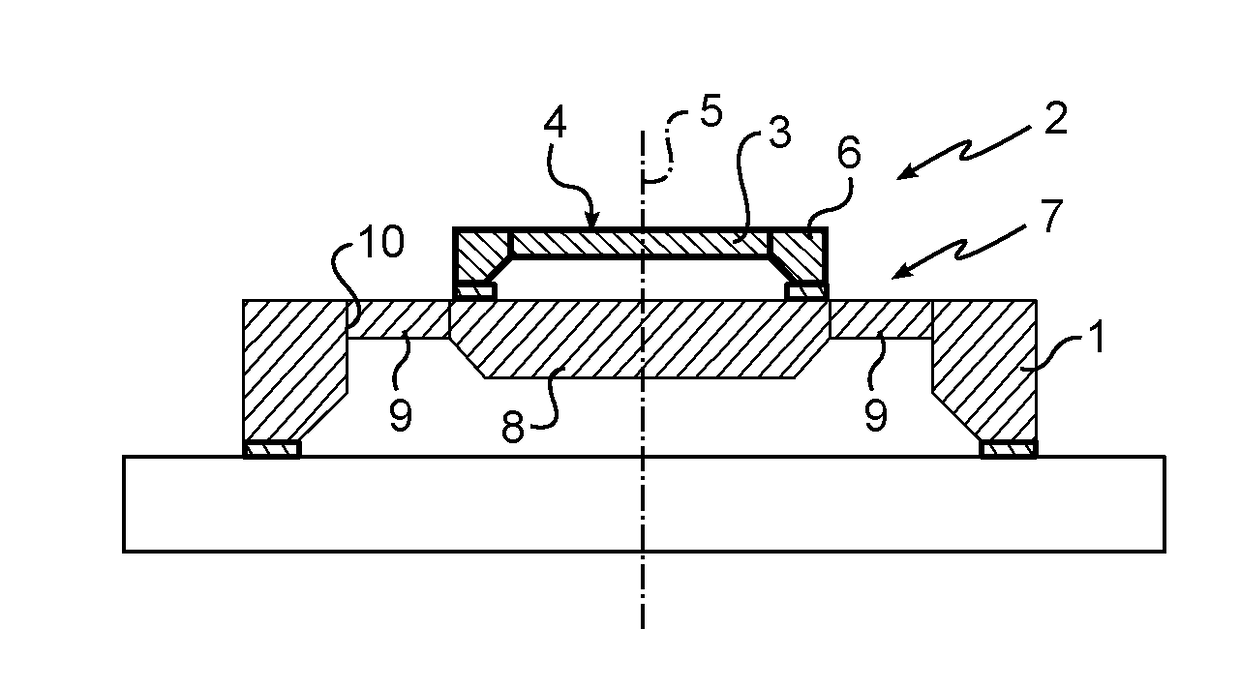
[0021] shown in FIGS. 1 to 3, the decoupling structure 7 comprises a plate 8 integral with the frame 6 and arms 9 extending between the plate 8 and the mount 1. The plate 8, the membrane 3 and the frame 6 are made of the same material. The arms 9 are elastically deformable so as to transform any differential thermal expansion between the mount 1 and the plate 8 into a resulting movement parallel to the mid-plane.

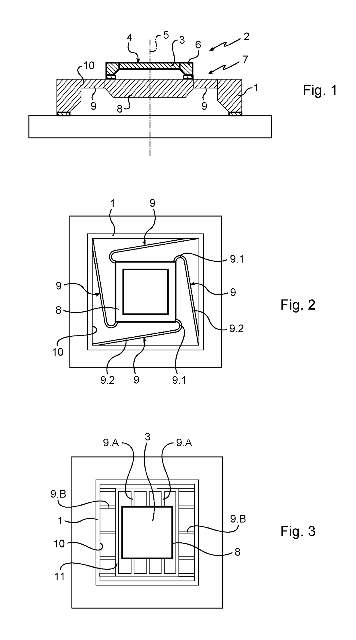
[0022]More precisely here, the plate 8 has a substantially rectangular perimeter and is accommodated in a recess 10 of the mount 1 having a rectangular perimeter, with the arms 9 connecting the perimeter of the plate 8 with the wall of the recess 10.

[0023]Referring to FIG. 2, the arms 9 have a curved portion 9.1 connected with the plate 8 and a straight portion 9.2 connected with the mount 1.

[0024]The curved portions 9.1 are curved in the same direction. The curved portion 9.1 of each arm 9 is integral with the plate 8 in the vicinity of one of the corners of the plate 8.

[00...

second embodiment

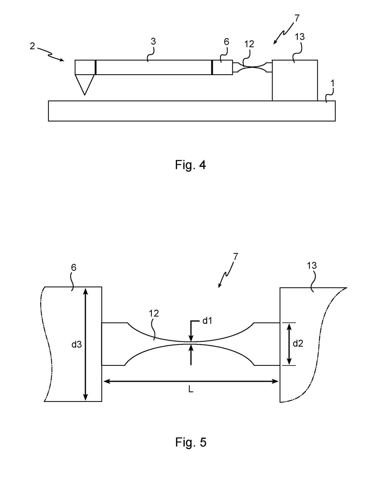
[0030]The elements identical with or similar to those previously described will bear reference numbers identical therewith in the following description of a second embodiment relating to FIG. 4.

[0031]In this embodiment, the decoupling structure 7 comprises a block 13 integral with the mount 1 and connected through a connection 12 to one side only of the frame 6, with the connection being so arranged that the frame extends in a cantilevered position relative to the mount 1.

[0032]The device is so arranged that the assembly consisting of the elements 2, 3, 6, 7 is made of materials having the same nature as the sensitive element, so as not to introduce any difference in the expansion between the sensitive element and the decoupling structure 7. The sensitive element can thus be assembled onto the decoupling structure 7 in a completely rigid way.

[0033]Such decoupling method is more particularly adapted to sensitive elements made of silicon, and of silicon alloy (silicon carbide, silicon...


PUM


Abstract

A pressure detection device including a mount whereon a pressure sensor is attached which comprises a membrane which has a surface intended to be subjected to a pressurized fluid and which is so arranged as to elastically deform according to pressure, and means for determining the deformation of the membrane along an axis normal to a mid-plane of the membrane in the rest state. The membrane is supported by a frame connected to the mount by a mechanical decoupling structure in order to isolate the membrane from stress resulting from a differential thermal expansion between the frame and the mount, with the membrane and the frame being made of the same material.

Description

[0001]The present invention relates to the field of pressure measurement, specifically in the field of aeronautics.STATE OF THE ART[0002]A pressure detection device comprises a mount whereon a pressure sensor is attached. The pressure sensor comprises a substrate supporting a first electrode and a membrane which supports a second electrode opposite the first electrode. The membrane is subjected to the pressure of the fluid to be measured, and is liable to deform under such pressure, so that the distance between the electrodes, measured along an axis normal to the electrodes varies according to pressure. As they are subjected to electric voltage, both electrodes thus form a capacitor, the capacity of which varies according to pressure, with the measurement of such capacity making it possible to determine pressure.[0003]Other devices including other means for measuring the deformation of the membrane also exist, such as strain gages, for instance.[0004]One drawback of such devices as ...

Claims


Application Information

Patent Timeline
IPC IPC(8): G01L19/14G01L19/06G01L7/08
CPCG01L19/146G01L19/0681G01L19/147G01L7/082
Inventor RIOU, JEAN-CHRISTOPHEBAILLY, ERIC
Owner SAFRAN ELECTRONICS & DEFENSE
Why Eureka
Try Eureka