Gear pump

a technology of gear pump and cylinder head, which is applied in the direction of pump components, machines/engines, liquid fuel engines, etc., can solve the problems of difficulty in completely suppressing the inflow of fluid into the cell with the smallest volume, and achieve the effect of reducing the volume of the inter-tooth chamber

Inactive Publication Date: 2018-06-21
AISIN AW CO LTD
View PDF2 Cites 1 Cited by
  • Summary
  • Abstract
  • Description
  • Claims
  • Application Information

AI Technical Summary

Benefits of technology

[0007]In the gear pump, the inter-tooth chamber which has been brought out of communication with the discharge port is brought into communication with the suction port while the volume of the inter-tooth chamber is decreased along with rotation of the inner rotor and the outer rotor. Consequently, a fluid is discharged from the inter-tooth chamber which has been brought out of communication with the discharge port to the suction port with the volume of the inter-tooth chamber decreased along with rotation of the inner rotor etc. The volume of the inter-tooth chamber which has been brought out of communication with the discharge port is increased after the inter-tooth chamber has been brought into communication with the suction port. That is, the volume of the inter-tooth cha...

Problems solved by technology

Even if the configuration described in Patent Document 1 is adopted, however, it is still difficult to completely suppress an inflow of a fluid into the cell with the s...

Method used


Image

  • Gear pump
  • Gear pump
  • Gear pump

Examples


Embodiment Construction

[0017]Now, an embodiment of the invention according to the present disclosure will be described with reference to the drawings.

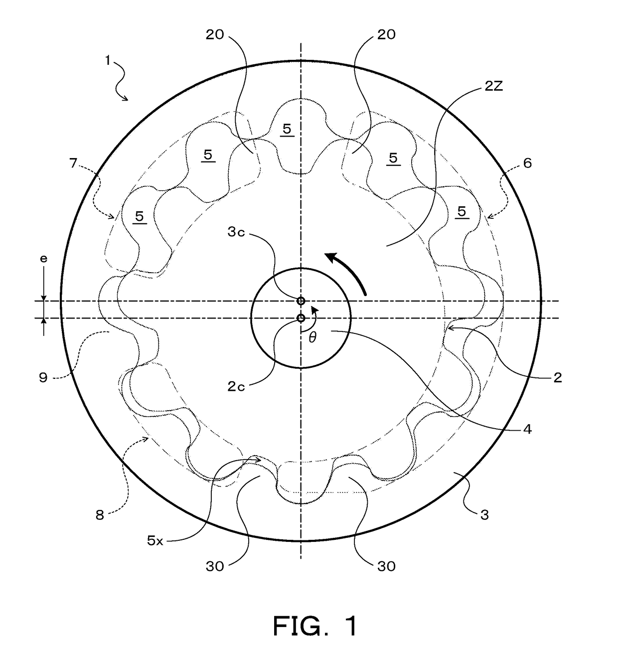
[0018]FIG. 1 is a diagram illustrating a schematic configuration of a gear pump 1 according to an embodiment of the present disclosure. The gear pump 1 illustrated in the drawing is constituted as an oil pump to be mounted on a vehicle (not illustrated), for example, and suctions working oil (ATF) stored in an oil pan and pumps the working oil to a hydraulic control device (none of such components is illustrated). The gear pump 1 includes a pump housing constituted from a pump body fixed to a transmission case of an automatic transmission and a pump cover fastened to the pump body (none of such components is illustrated), for example, and an inner rotor (drive gear) 2 and an outer rotor (driven gear) 3 that are rotatably disposed in a gear housing chamber (not illustrated) defined by the pump housing. The gear pump 1 may be constituted as an on-vehicle pump ...


PUM


Abstract

A gear pump having a suction port, first and second discharge ports, an inner rotor having external teeth, an outer rotor having internal teeth such that the number of the internal teeth is larger than that of the external teeth of the inner rotor, and inter-tooth chambers defined by the external teeth and the internal teeth. The first and second discharge ports are in communication with the inter-tooth chamber whose volume is decreased along with rotation of the inner rotor etc. An inter-tooth chamber which has been brought out of communication with the second discharge port is brought into communication with the suction port while the volume is decreasing. The volume of the inter-tooth chamber which has been brought out of communication with the second discharge port is increased after at least a part of the inter-tooth chamber has been brought into communication with the suction port.

Description

TECHNICAL FIELD[0001]The present disclosure relates to a gear pump that includes an inner rotor having a plurality of external teeth and an outer rotor having a plurality of internal teeth and disposed eccentrically with respect to the inner rotor.BACKGROUND ART[0002]There has hitherto been known a gear pump that includes an inner rotor having n external teeth, an outer rotor having (n+1) internal teeth meshed with the external teeth, and a casing formed with a suction port and a discharge port (see Patent Document 1, for example). In the gear pump, a first angle formed by a first line that connects between the center of rotation of the inner rotor and the tooth tip of the external teeth and a second line that connects between the center of rotation and a meshing portion of the external teeth is 1.4 times or more and 1.8 times or less a second angle formed by a third line that connects between the center of rotation and the tooth bottom of the external teeth and the second line. The...

Claims


Application Information

Patent Timeline
IPC IPC(8): F04C2/08F04C2/10
CPCF04C2/084F04C2/102F04C2240/20F04C2250/20F04C2210/206
Inventor HATTORI, MASASHITAKEDA, MITSUHIROKIMURA, MASAYUKI
Owner AISIN AW CO LTD
Why Eureka
Try Eureka