
Automated pipette manipulation system

a pipette and automatic technology, applied in the field of automatic pipette manipulation system, can solve the problems of mechanical pipette still occupying liquid handling constitutes a fundamental building block of most tests, and pipetting may occupy a considerable percentage of time for a technician, etc., to achieve accurate, cost-efficient, and robust

Active Publication Date: 2018-06-07
HABBAL WALID
View PDF19 Cites 14 Cited by
  • Summary
  • Abstract
  • Description
  • Claims
  • Application Information

AI Technical Summary

Benefits of technology

The present invention is an automated system for manipulating pipettes and measuring the amount of liquid aspired and dispensed accurately and easily. It is cost-efficient and can be used with any commercial pipette, regardless of brand or manufacturer. The system includes a simple and quick calibration process. Overall, the invention provides a better and more reliable method for measuring liquids than previous methods in the prior art.

Problems solved by technology

In particular, liquid handling constitutes a fundamental building block in most tests performed in said laboratories.
However, mechanical pipettes still represent a large fraction of the market because they are more economical, robust, and simpler to operate.
In a typical laboratory environment, pipetting may occupy a considerable percentage of time for a technician.
Pipette users perform extremely large numbers of operations to dispense measured volumes of reagents and solutions.
The cost of automated devices is linked to their complexity and cost of the components used.
However, these systems are costly and difficult to maintain and service.
However, the use of a pipette not integrated or connected to the entire system, adversely affects the accuracy of the volumetric measurements.
However, these cameras or automated vision systems are costly, challenging to maintain and calibrate, not sufficiently robust, and sensitive to elements within a laboratory, such as temperature, dust, light, and the like.
Unless this and other practical problems associated with automated pipette manipulation systems are solved, many laboratories will continue to sacrifice accuracy and robustness by utilizing other systems or technicians prone to human error.

Method used


Image

  • Automated pipette manipulation system
  • Automated pipette manipulation system
  • Automated pipette manipulation system

Examples


Embodiment Construction

[0024]Reference will now be made to the drawings in which various elements of the present invention will be given numerical designations and in which the invention will be discussed so as to enable one skilled in the art to make and use the present invention.

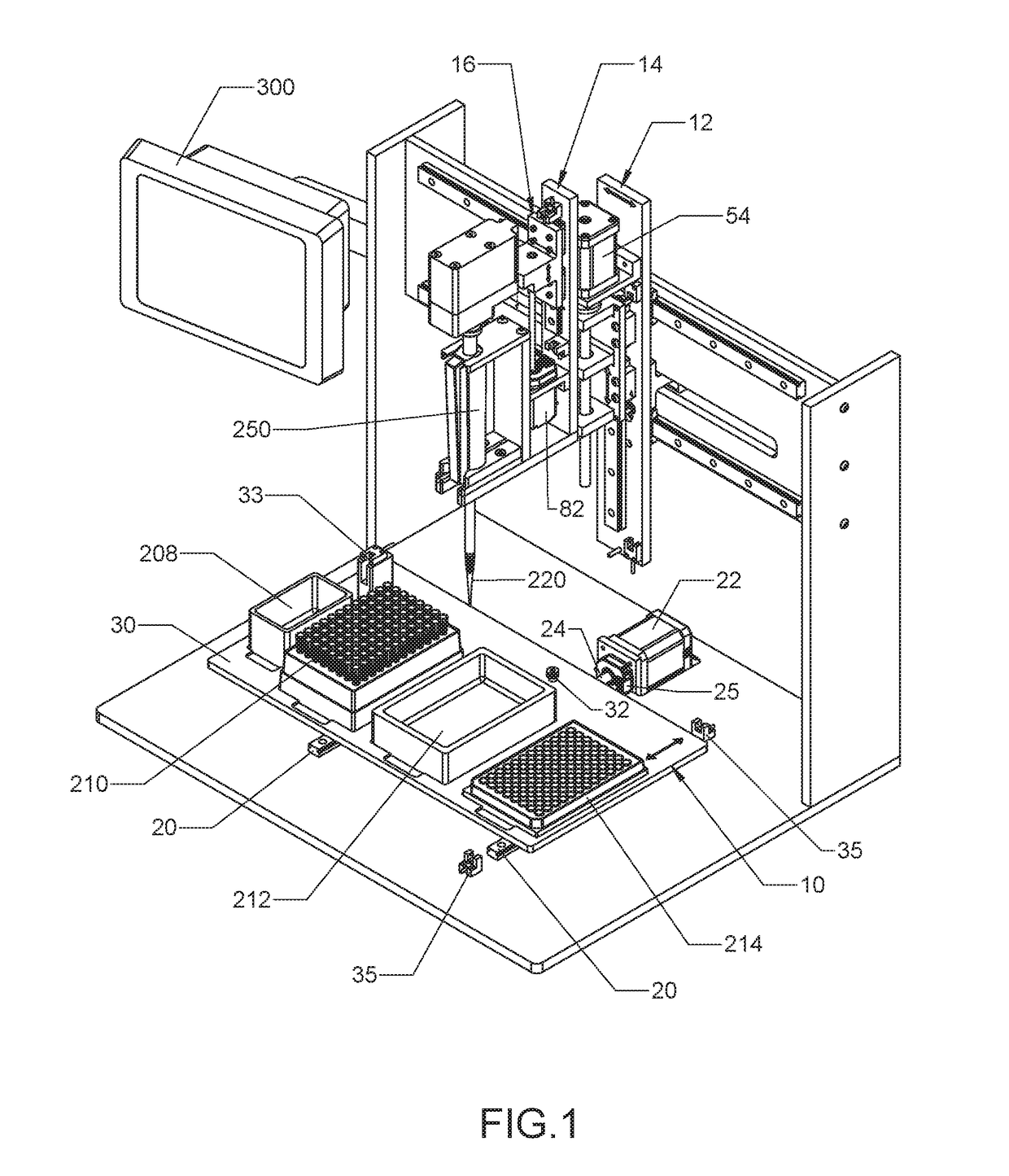
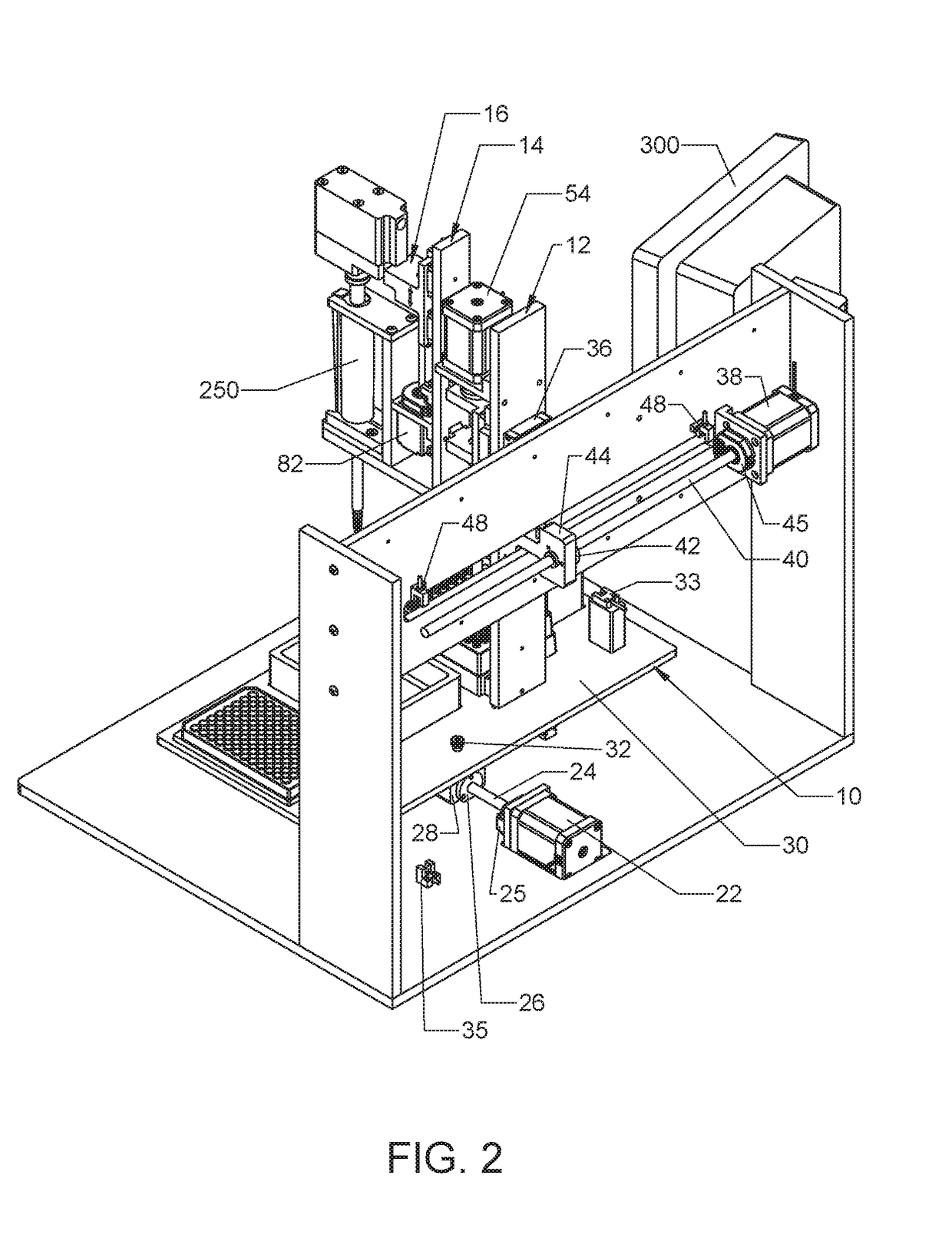
[0025]The present invention is an automated pipette manipulation system 500 that comprises a platform assembly 10, a head assembly 12, an actuator head assembly 14, an actuator mechanism 16, a pipette 250, and a microprocessor 300. The head assembly 12 allows for horizontal movement of the pipette 250 along the x-axis. The actuator head assembly 14 allows for vertical movement of the pipette 250 along the z-axis. The actuator mechanism 16 manipulates the pipette 250 to aspire or dispense liquid, and extract a pipette tip 220 that is attached to the pipette 250. Finally, the platform assembly 10 can be moved horizontally in the direction that is transverse of the horizontal movement of the head assembly 12, thus, along the y-axis...


PUM


Abstract

The automated pipette manipulation system of the present invention allows for the automated manipulation of any pipette commercially available to aspire and dispense liquids in a chemical or biochemical laboratory setting. Measuring the amount of liquid aspired or dispensed by a pipette is conducted by a load sensor that records the starting point of the displacement of a pushbutton of said pipette and a motor that drives the displacement of said pushbutton a predetermined distance past the starting point that corresponds to a predetermined volume of liquid aspired or dispensed by said pipette. The automated pipette manipulation system of the present invention further detects whether a pipette tip is attached to said pipette and then automatically ejects said pipette tip at the end of a liquid handling process.

Description

[0001]This document claims priority to Provisional Patent Application No. 62 / 421,023 filed on Nov. 11, 2016.FIELD OF INVENTION[0002]The present invention relates to an automated pipette manipulation system used in chemical and biochemical laboratories. More particularly, the present invention is an apparatus or methods for manipulation of a laboratory pipette in a programmable manner allowing the user to instruct the device to transfer fluid in one receptacle to another.DESCRIPTION OF PRIOR ART[0003]A wide variety of automated diagnostic instruments are used in chemical and biochemical laboratories. In particular, liquid handling constitutes a fundamental building block in most tests performed in said laboratories. Liquid handling is defined as the operation of putting one sample in contact with another while being able to quantify the amount of liquid used. Typically, liquid handling is performed either manually by human operators or by means of automatic devices of various types. ...

Claims


Application Information

Patent Timeline
Patent Type & Authority Applications(United States)
IPC IPC(8): B01L3/02
CPCB01L3/0289B01L3/0237B01L2200/025B01L3/0227G01N35/1011G01N2035/1013
Inventor HABBAL, WALID
Owner HABBAL WALID
Learn More