
Air motion transformer passive radiator for loudspeaker

a passive radiator and air motion technology, applied in the direction of transducer details, diaphragm damping, electrical transducers, etc., can solve the problems of large mechanical vibration passing onto the loudspeaker cabinet through the passive radiator frame, the single moving diaphragm of a conventional passive radiator must be very large, and the available area is restricted. achieve the effect of limiting the overexcursion of moving components and high output levels

Active Publication Date: 2018-05-31
CHRISTENSEN EUGENE JULIUS
View PDF1 Cites 3 Cited by
  • Summary
  • Abstract
  • Description
  • Claims
  • Application Information

AI Technical Summary

Benefits of technology

The present invention is an improvement on passive radiator technology by using a stacked design with multiple moving diaphragm sections that move towards or away from each other as air pressure or sound waves from the back of the speaker impact the diaphragms. Magnetic sections can be attached to the moving parts for better suspension and to prevent over-excursion at high output levels. Overall, this design provides better sound quality and reduced distortion.

Problems solved by technology

One of the main drawbacks of conventional passive radiators is that the single moving diaphragm of a conventional passive radiator must be made very large, or must have a large amount of linear travel available, or must have both, in order to provide low-distortion, low-frequency sound.
This implies that a conventional passive radiator will occupy a large amount of surface area when mounted on the surface of a loudspeaker cabinet, and this large area requirement restricts the available areas where a conventional passive radiator may be mounted on a loudspeaker cabinet.
Another drawback of conventional passive radiators is that large amounts of mechanical vibration are passed onto the loudspeaker cabinet through the passive radiator frame as the moving parts of the passive radiator vibrate back and forth.
A third drawback of conventional passive radiators is the large amount of linear travel typically required, resulting in unwanted, distorted modes of movement such as rocking and non-linear motion at the extremes of excursion.

Method used


Image

  • Air motion transformer passive radiator for loudspeaker
  • Air motion transformer passive radiator for loudspeaker
  • Air motion transformer passive radiator for loudspeaker

Examples


Embodiment Construction

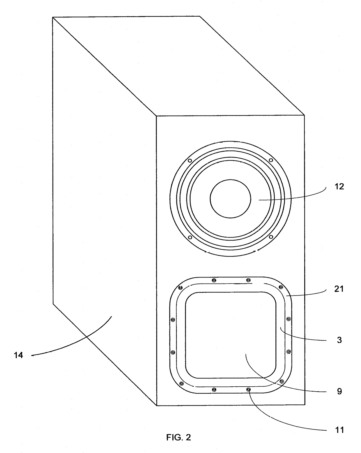
[0025]This invention relates to a device which can be used to augment the production of low frequency sounds emanating from a loudspeaker cabinet 14 which also contains one or more low frequency active drivers such as a conventional moving coil and cone woofer 12.

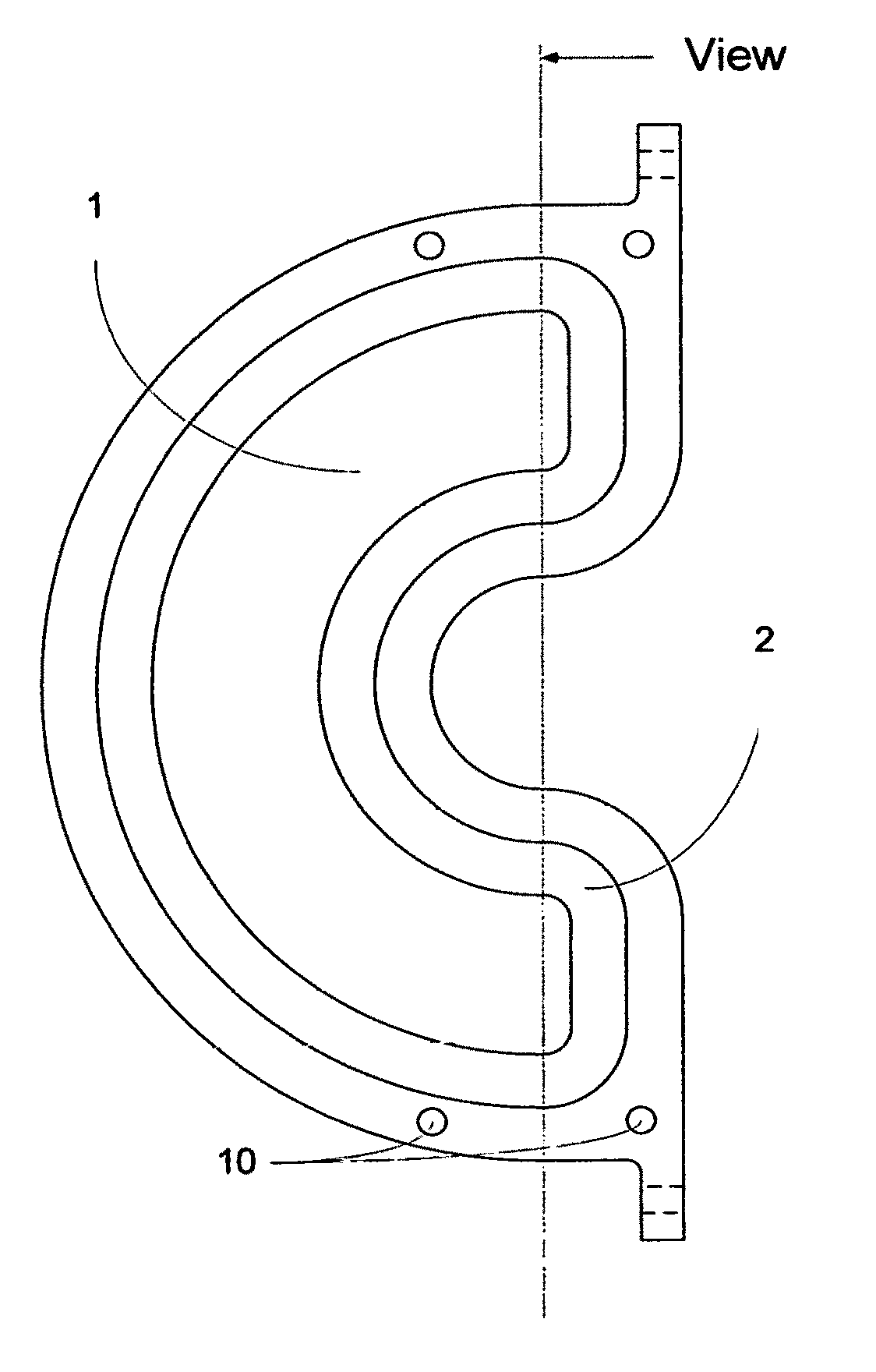
[0026]The moving diaphragms or diaphragm sections of the present invention are arranged in generally parallel coaxial layers, with semi-confined air spaces 20 located between the moving diaphragms or diaphragm sections which have air openings 3 and 4 which alternate between the outer edges and the inner edges of the semi-confined air spaces 20 between and proximate adjacent diaphragm assembly layers.

[0027]A relatively positive and temporary air pressure zone located proximate the interior of the present invention and inside the loudspeaker cabinet 14, causes sound waves to propagate outward into the listening space from the exterior of the passive radiator device, while a relatively negative and temporary air pressure zone ...


PUM


Abstract

The present invention provides an improved passive radiator device by utilizing a stacked construction in which there exist two or more generally parallel and separate movable diaphragm sections, in which the relative motion of adjacent diaphragm sections will either move toward each other, or away from each other, as air pressure or sound waves emanating from the interior of a loudspeaker cabinet impinges upon the interior air openings of the present invention.

Description

CROSS-REFERENCE TO RELATED APPLICATIONS[0001]This application claims priority for U.S. Provisional Patent Application 62 / 386,474 dated Dec. 3, 2015 and US Provisional Patent Application 62 / 387,109 dated Dec. 23, 2015.BACKGROUND OF THE INVENTIONField of the Invention[0002]This invention relates generally to loudspeaker passive radiator devices.Description of Related Art[0003]Conventional loudspeaker passive radiator devices, sometimes also known as ‘drone cones’, have been available for many decades, at least as far back as 1954, as mentioned in the Journal of the Audio Engineering Society, (Vol. II, No. 4, p. 219), Harry F. Olson, et al. The purpose and function of a passive radiator is to provide passive means for extending the low-frequency response of a loudspeaker system through the resonant motion of a suspended, movable panel or surface which has the appropriate mass and spring constant properties to correctly interact with the desired low frequencies of sound waves emanating ...

Claims


Application Information

Patent Timeline
Patent Type & Authority Applications(United States)
IPC IPC(8): H04R1/28H04R7/26
CPCH04R1/2834H04R9/06H04R7/26
Inventor CHRISTENSEN, EUGENE JULIUS
Owner CHRISTENSEN EUGENE JULIUS
Learn More