Image display device and light guiding device
a technology of image display and light guiding, which is applied in the field of image display device and light guiding device, can solve the problems of reducing resolution and reducing image resolution, and achieve the effect of less resolution reduction
- Summary
- Abstract
- Description
- Claims
- Application Information
AI Technical Summary
Benefits of technology
Problems solved by technology
Method used
Image

Examples
embodiment 1
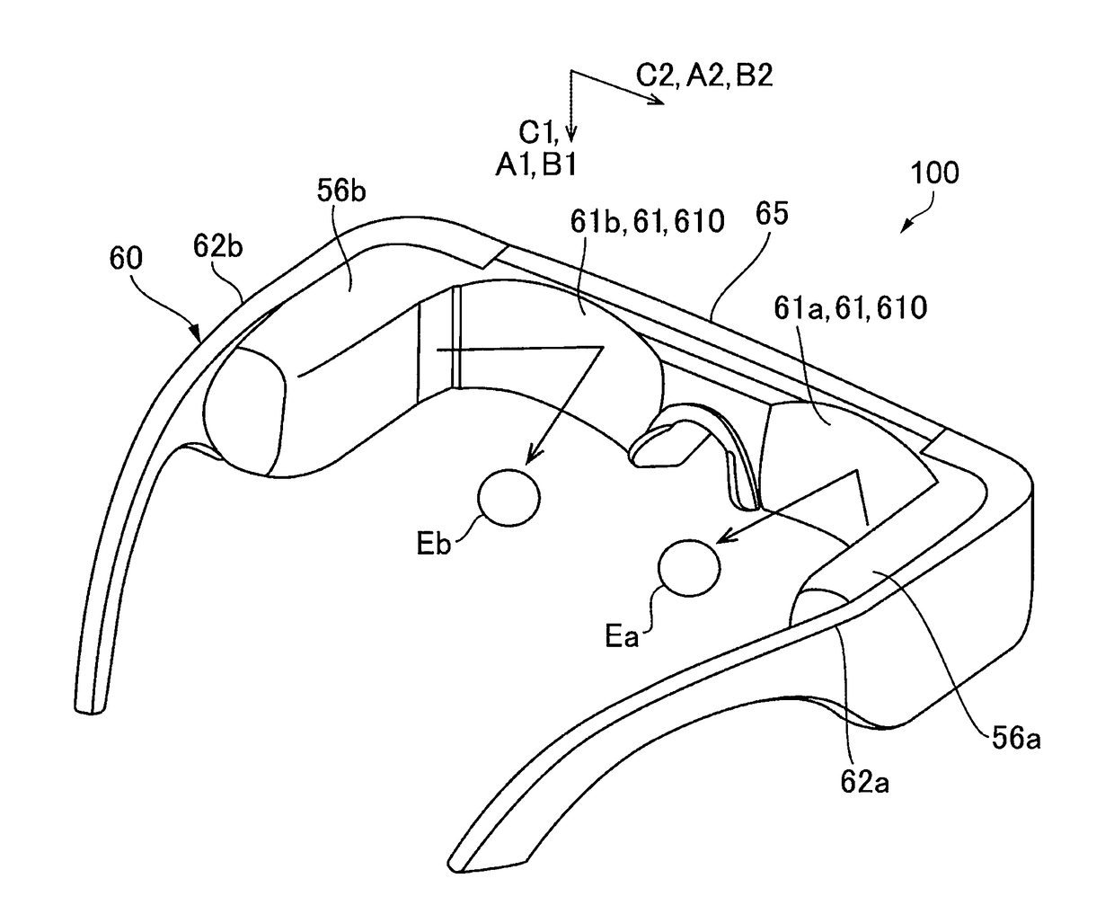
[0046]FIG. 1 is an external view illustrating an aspect of appearance of an image display device 100 to which the embodiment is applied.
[0047]In FIG. 1, the image display device 100 is a head-mount image display device and includes a right eye image light generation unit 56a, a right eye deflection member 61a configured to deflect image light emitted from the right eye image light generation unit 56a and make the image light incident on an observer's right eye Ea, a left eye image light generation unit 56b, and a left eye deflection member 61b configured to deflect the image light emitted from the left eye image light generation unit 56b and make the image light incident on an observer's left eye Eb. For example, the image display device 100 has a form resembling eyeglasses. Specifically, the image display device 100 includes a frame 60 configured to hold the right eye image light generation unit 56a, the right eye deflection member 61a, the left eye image light generation unit 56b,...
modification 1
[0075]In Modification 1, one mode of the first diffraction element 61 and the second diffraction element 31 will be described where image light represents a color image. Note that, the same constituents as those of Embodiment 1 are denoted by the same reference numerals, and repeated description thereof will be omitted. Furthermore, as in Embodiment 1, the first diffraction element 61 and the second diffraction element 31 have the same basic configuration, and therefore only a configuration of the first diffraction element 61 will be described here, and description of the second diffraction element 31 will be omitted.
[0076]FIG. 6 is a sectional view illustrating the first diffraction element 61 according to Modification 1. In Modification 1, the first diffraction element 61 includes reflective volume holographic elements 610R, 610G, and 610B which are stacked one on another, and the reflective volume holographic elements 610R, 610G, and 610B have interference fringes 611R, 611G, and...
modification 2
[0082]In Modification 2, another mode of the first diffraction element 61 and the second diffraction element 31 will be described where image light represents a color image. Note that, the same constituents as those of Embodiment 1 are denoted by the same reference numerals, and repeated description thereof will be omitted. Furthermore, as in Embodiment 1, the first diffraction element 61 and the second diffraction element 31 have the same basic configuration, and therefore only a configuration of the first diffraction element 61 will be described here, and description of the second diffraction element 31 will be omitted.
[0083]FIG. 8 is a sectional view illustrating the first diffraction element 61 according to Modification 2. In Modification 2, the first diffraction element 61 includes the reflective volume holographic element 610, and has a configuration in which the interference fringes 611R, 611G, and 611B are superimposed on one another.
[0084]As in Modification 1, each of the i...
PUM
 Abstract
Description
Claims
Application Information
 - R&D
- Intellectual Property
- Life Sciences
- Materials
- Tech Scout
- Unparalleled Data Quality
- Higher Quality Content
- 60% Fewer Hallucinations
Browse by: Latest US Patents, China's latest patents, Technical Efficacy Thesaurus, Application Domain, Technology Topic, Popular Technical Reports.
© 2025 PatSnap. All rights reserved.Legal|Privacy policy|Modern Slavery Act Transparency Statement|Sitemap|About US| Contact US: help@patsnap.com