
Optical hazard detection

a technology optical hazard detection, which is applied in the field of optical hazard detection, can solve the problems of powerlines posing hazards for operators of aerial devices and other elevating equipment, and hazards for operators

Active Publication Date: 2018-05-24
ALTEC INDS
View PDF6 Cites 2 Cited by
  • Summary
  • Abstract
  • Description
  • Claims
  • Application Information

AI Technical Summary

Benefits of technology

This patent describes an optical hazard detection system for aerial devices. The system uses an optical sensor to capture images and a controller to identify hazards based on the images. The controller then creates a hazard zone to prevent the aerial device from hitting the hazard. This system helps to prevent accidents and improve safety during operation.

Problems solved by technology

Powerlines pose a risk to operators of aerial devices and other elevating equipment.
However, if the utility platform strikes the power line, damage to both the utility platform and the power line can result, and (while unlikely) an electrical discharge through the aerial device could result creating hazards for the operator.

Method used


Image

  • Optical hazard detection
  • Optical hazard detection
  • Optical hazard detection

Examples


Embodiment Construction

[0016]The following detailed description references the accompanying drawings that illustrate specific embodiments in which the invention can be practiced. The embodiments are intended to describe aspects of the invention in sufficient detail to enable those skilled in the art to practice the invention. Other embodiments can be utilized and changes can be made without departing from the scope of the invention. The following detailed description is, therefore, not to be taken in a limiting sense. The scope of the invention is defined only by the appended claims, along with the full scope of equivalents to which such claims are entitled.

[0017]In this description, references to “one embodiment,”“an embodiment,” or “embodiments” mean that the feature or features being referred to are included in at least one embodiment of the technology. Separate references to “one embodiment,”“an embodiment,” or “embodiments” in this description do not necessarily refer to the same embodiment and are a...


PUM


Abstract

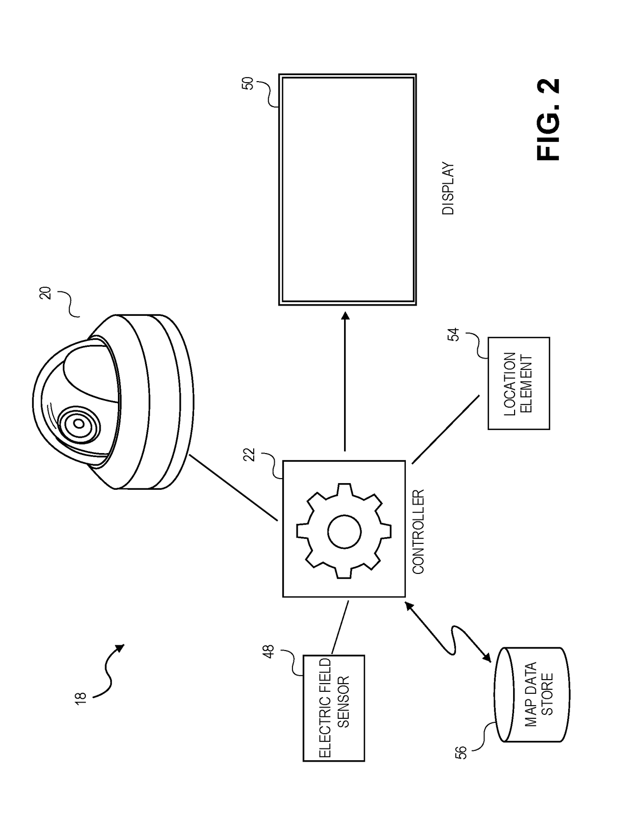
An optical hazard detection system is described that may be used with an aerial device. The optical hazard detection system is utilized for determining a hazard in proximity thereto. The system comprises an optical sensor and a controller. The optical sensor is configured to capture optical images. The controller is configured to acquire the optical images from the optical sensor. The controller is also configured to identify a hazard at least in part from the optical images and to establish a hazard zone to prevent the utility platform from striking the hazard. The hazard zone is within a deployable range for the aerial device.

Description

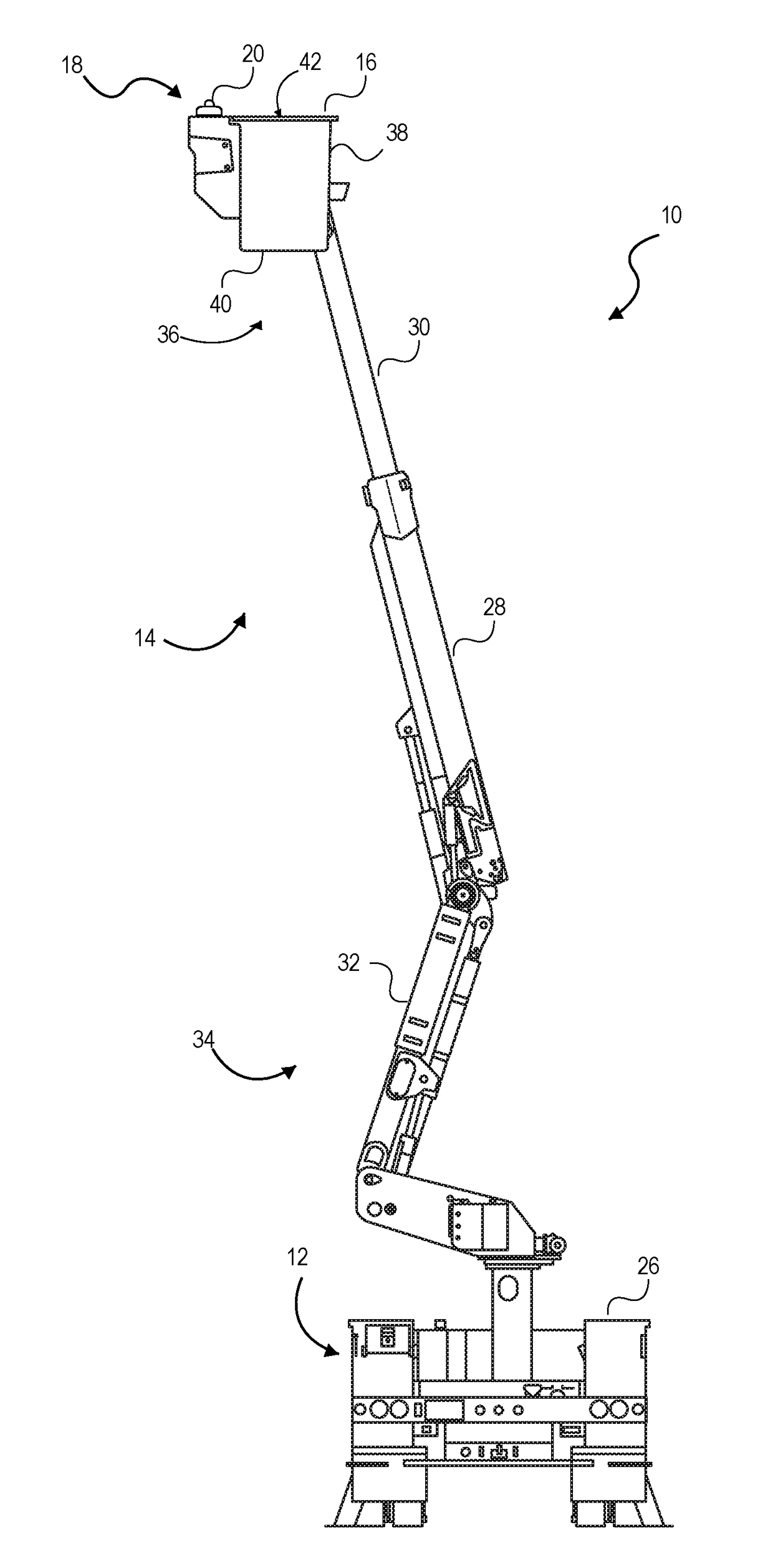
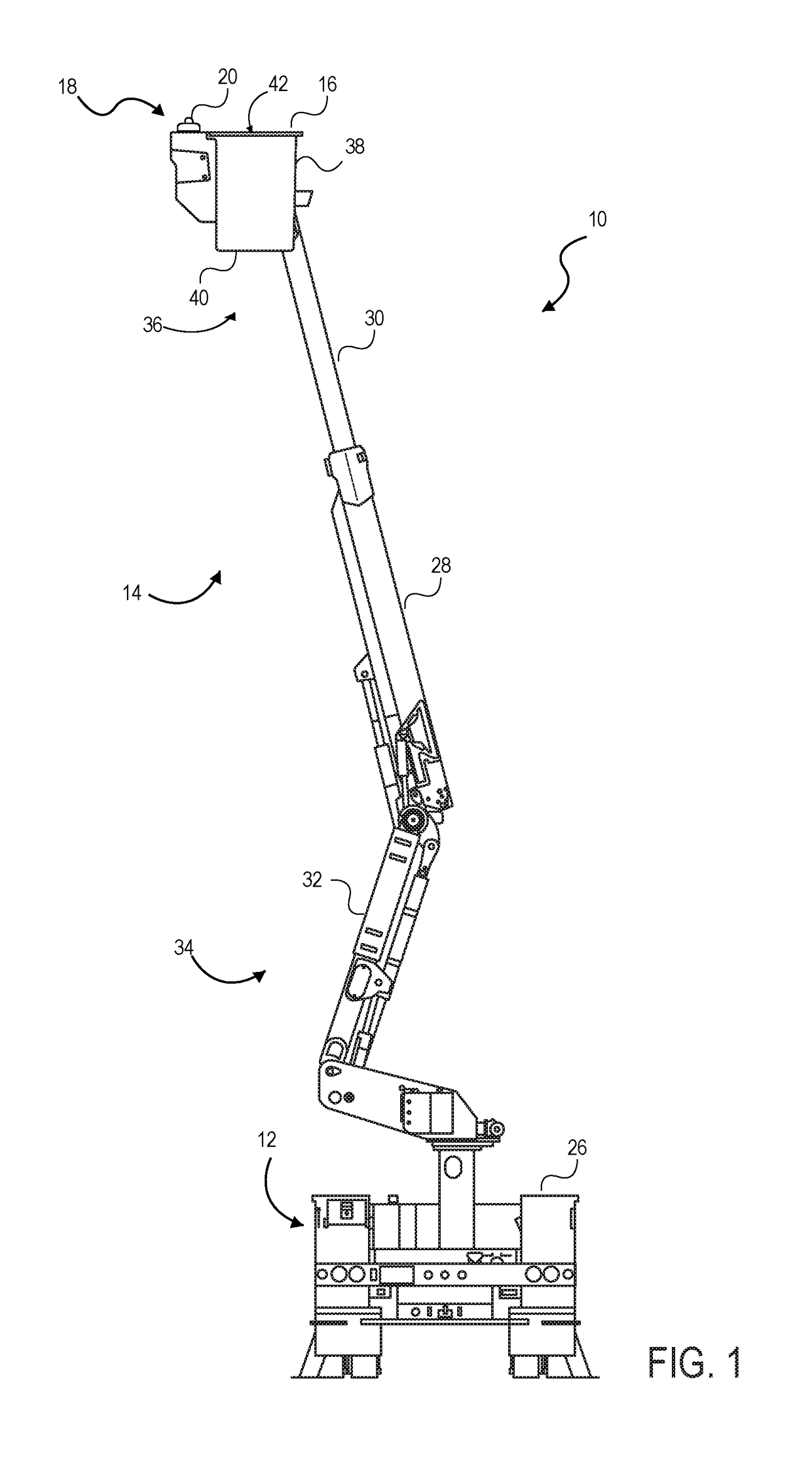
BACKGROUND1. Field[0001]Embodiments of the invention relate to the detection and avoidance of hazards. More specifically, embodiments of the invention relate to the detection and avoidance of hazards by aerial devices and other heavy machinery.2. Related Art[0002]Powerlines pose a risk to operators of aerial devices and other elevating equipment. Typically, aerial devices are used to repair and replace power and communication lines. As such, a utility platform of the aerial device may need to move near a powerline. However, if the utility platform strikes the power line, damage to both the utility platform and the power line can result, and (while unlikely) an electrical discharge through the aerial device could result creating hazards for the operator. To prevent such collisions, operators typically must visually identify hazards and not move the utility platform into them.SUMMARY[0003]Embodiments of the invention address the above-mentioned problems by providing an optical hazard ...

Claims


Application Information

Patent Timeline
IPC IPC(8): H04N7/18G06K9/00G08B7/06G08B6/00
CPCH04N7/183G08B6/00G08B7/06G06K9/00771G06V20/52
Inventor CHARD, JOSHUA T.
Owner ALTEC INDS
Learn More