
Anti-collision system and Anti-collision method

an anti-collision system and anti-collision technology, applied in the direction of programmed manipulators, instruments, programme control, etc., can solve the problems of affecting the operation precision of each axis affecting the maintenance cost of the automatic robotic arm, and affecting the accuracy of the operation. , to achieve the effect of preventing the breakdown of the servo motor

Inactive Publication Date: 2018-05-24
INSTITUTE FOR INFORMATION INDUSTRY
View PDF7 Cites 6 Cited by
  • Summary
  • Abstract
  • Description
  • Claims
  • Application Information

AI Technical Summary

Benefits of technology

The anti-collision system and method use a vision processing unit to recognize objects and estimate their movement paths. It then determines if the object will collide with the robotic arm based on the arm's movement path and the object's movement path. If there is a sudden object entry, the system can stop the arm or enter an adaptation mode to prevent stress and breakdown. The technical effect of this system is to prevent collisions between the robotic arm and objects, reducing the risk of damage and downtime.

Problems solved by technology

When an unexpected collision is happened, the operation precisions of each axis of the automatic robotic arm will be impacted.
Further, the unexpected collision may damage the servo motor or the components.
Therefore, the time and the cost of maintaining the automatic robotic arm are higher than other precision machineries.
As such, how to detect that whether an unexpected object enters the operation region of the automatic robotic arm when the automatic robotic arm is operating, and how to immediately adjust the operation status of the automatic robotic arm when the unexpected object enters the operation region of the automatic robotic arm for preventing the servo motor from damage becomes a problem to-be solved in the art.

Method used


Image

  • Anti-collision system and Anti-collision method
  • Anti-collision system and Anti-collision method
  • Anti-collision system and Anti-collision method

Examples


Embodiment Construction

[0015]Reference will now be made in detail to the present embodiments of the disclosure, examples of which are illustrated in the accompanying drawings. Wherever possible, the same reference numbers are used in the drawings and the description to refer to the same or like parts.

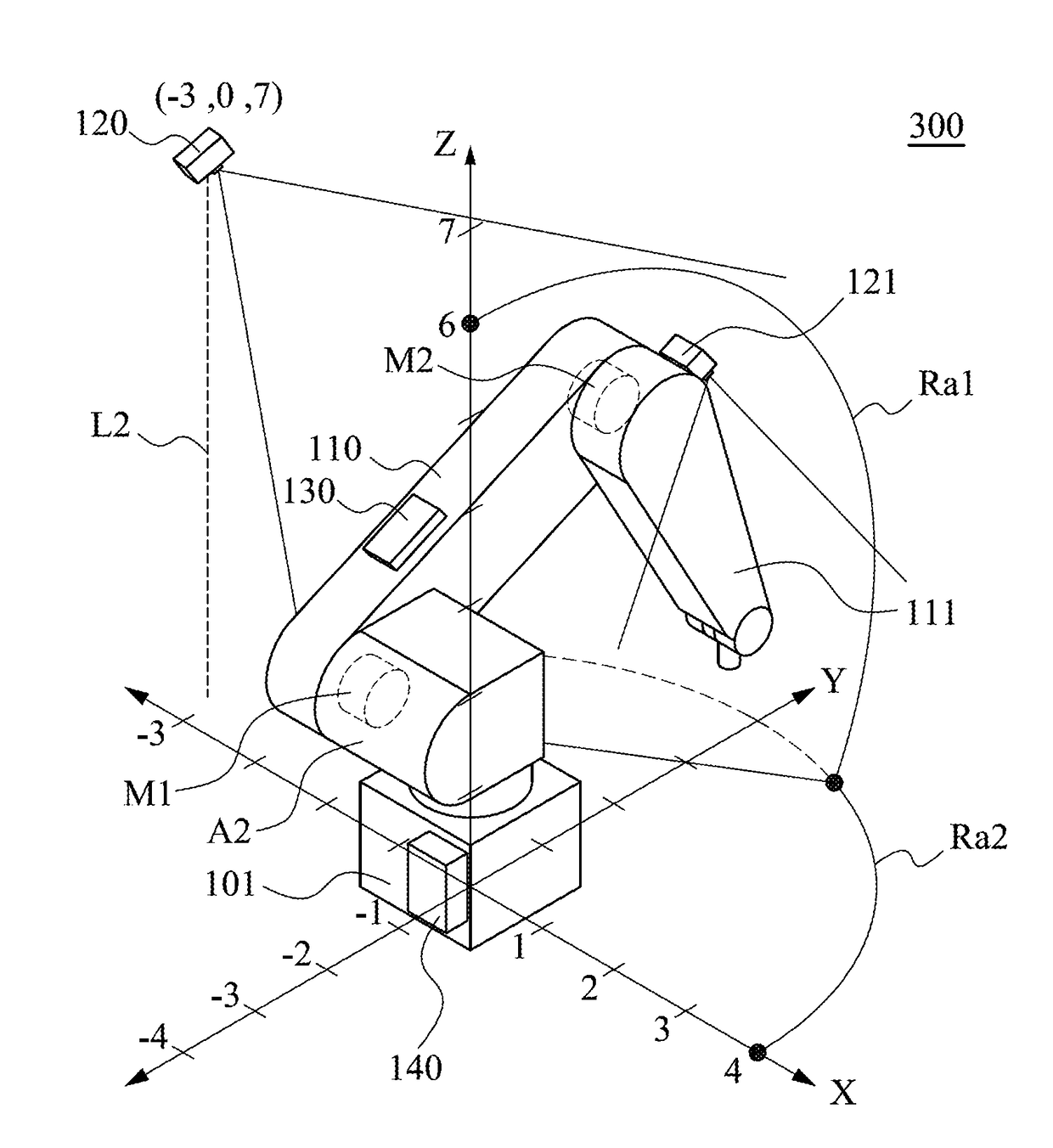
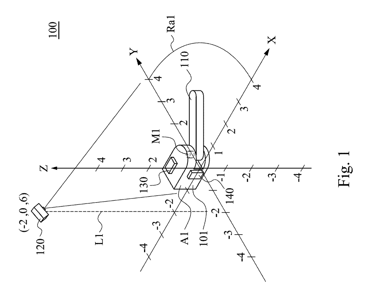
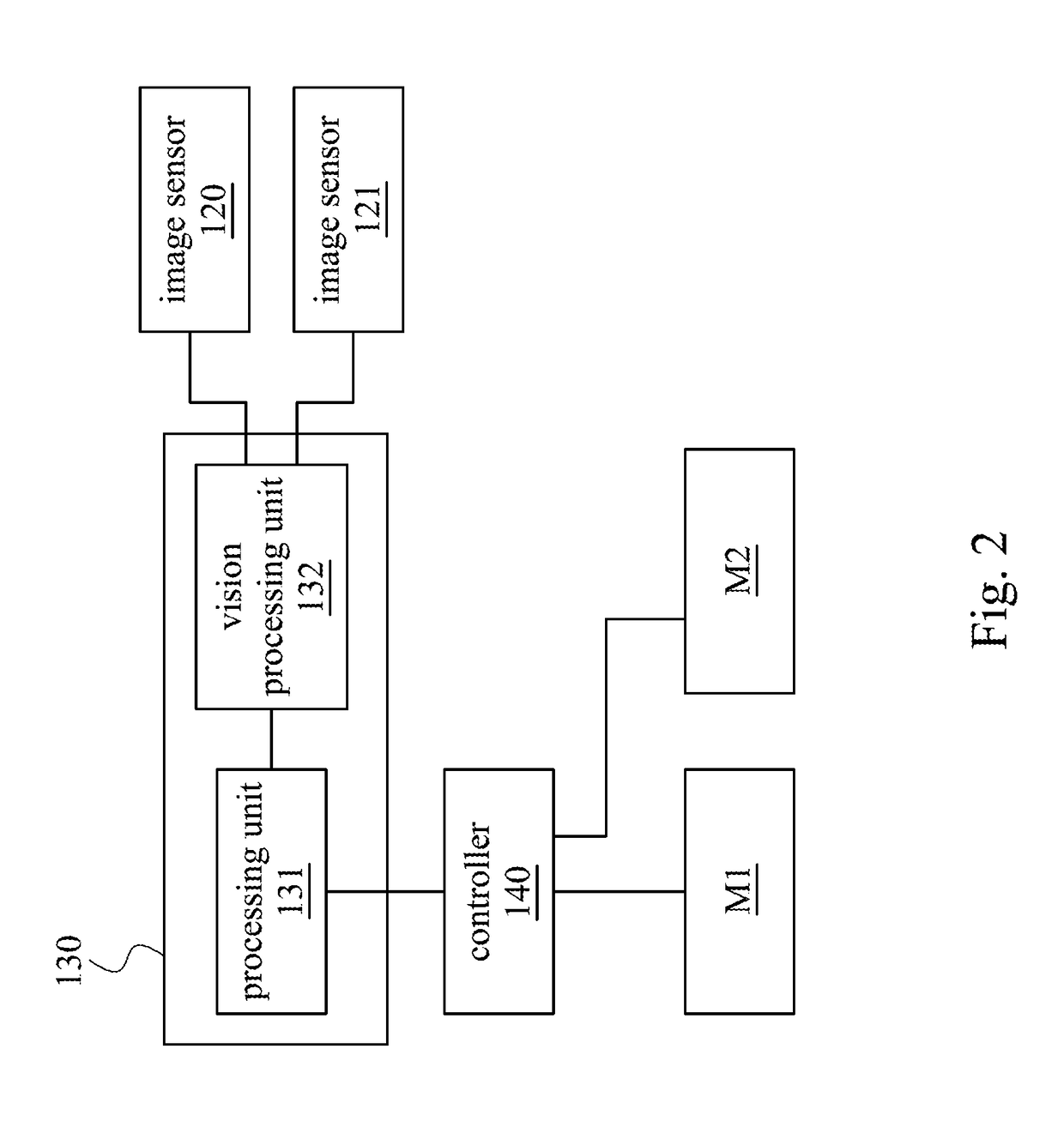
[0016]References are made to FIGS. 1-2, FIG. 1 depicts a schematic diagram of an anti-collision system 100 according to one embodiment of present disclosure. FIG. 2 depicts a schematic diagram of an embedded system 130 according to one embodiment of present disclosure. In one embodiment, the anti-collision system 100 uses for preventing an object from colliding with an automatic robotic arm A1. The automatic robotic arm A1 includes a controller 140. The controller 140 can be connected to an external computer. The operation method of the automatic robotic arm A1 can be configured by a user through application software installed in the external computer. And, the application software can transfer the operation ...


PUM


Abstract

An anti-collision system uses for preventing an object collide with automatic robotic arm. Wherein, the automatic robotic arm includes a controller. The anti-collision system includes a first image sensor, a vision processing unit and a processing unit. The first image sensor captures a first image. The vision processing unit receives the first image, recognizes the object of the first image and estimates an object movement estimation path of the object. The processing unit is coupled to the controller to access an arm movement path. The processing unit estimates an arm estimation path of the automatic robotic arm, analyzes the first image to establish a coordinate system, and determines whether the object will collide with the automatic robotic arm according to the arm estimation path of the automatic robotic arm and the object movement estimation path of the object.

Description

CROSS-REFERENCE TO RELATED APPLICATION[0001]This application claims priority to Taiwan Application Serial Number 105138684, filed Nov. 24, 2016, which is herein incorporated by reference.BACKGROUNDTechnical Field[0002]The present disclosure relates to an anti-collision system and an anti-collision method. More particularly, the present disclosure relates to an anti-collision system and an anti-collision method applied to an automatic robotic arm.Description of Related Art[0003]In general, the automatic robotic arm is one kind of precision machineries composed of rigid bodies and servo motor. When an unexpected collision is happened, the operation precisions of each axis of the automatic robotic arm will be impacted. Further, the unexpected collision may damage the servo motor or the components. The components in automatic robotic arm are assembled as continuous structures. Thus, all the components need to be changed in the same time when updating the components of the automatic robo...

Claims


Application Information

Patent Timeline
Patent Type & Authority Applications(United States)
IPC IPC(8): B25J9/16
CPCB25J9/1666G05B2219/40442G05B2219/40476B25J9/1697B25J9/1676
Inventor TSAO, WEI-HUANLIN, CHIH-CHIEHCHIU, HUNG-SHENGCHANG, HSIAO-CHEN
Owner INSTITUTE FOR INFORMATION INDUSTRY
Learn More