Station and method for filling a tank with a fuel gas

Active Publication Date: 2018-05-03
LAIR LIQUIDE SA POUR LETUDE & LEXPLOITATION DES PROCEDES GEORGES CLAUDE
View PDF17 Cites 7 Cited by
  • Summary
  • Abstract
  • Description
  • Claims
  • Application Information

AI Technical Summary

Benefits of technology

The use of gas stores in filling stations has several advantages. This structure helps to optimize the use of these stores, reducing the number of source stores needed and even eliminating the need for cascade filling. The system also allows for physical separation between hydrogen and compression fluid, leading to isobaric filling and reducing pressure variations. The transfer of gas can be done at constant pressure, simplifying the design of downstream heat exchangers. The method includes transferring gas from a source store while injecting liquid to prevent pressure drops or rises. The overall effect of the patent text is to provide an efficient and reliable approach for gas storage and filling in fuel stations.

Problems solved by technology

Moreover, this solution entails installing in the station high-capacity high-pressure stores since only a portion of the contents is actually transferred into the tank of the vehicle by such balancing (high residual quantities).
This necessitates the installation of a complex system of valves.

Method used


Image

  • Station and method for filling a tank with a fuel gas
  • Station and method for filling a tank with a fuel gas

Examples


Embodiment Construction

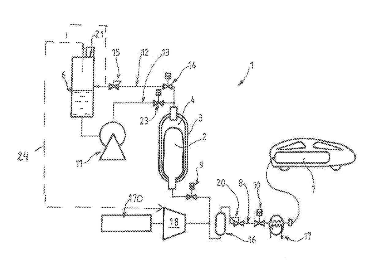
[0038]The example of a filling station 1 shown in FIG. 1 conventionally includes a source store 3 of fuel gas (such as hydrogen) and a gas transfer circuit 8. The gas transfer circuit 8 has an upstream first end connected to the source store 3 and a downstream second end intended to be in fluid communication with the tank 7 to be filled (for example via a quick-connect system at the end of a hose).

[0039]The gas transfer circuit 8 includes at least one valve 9, 10 for controlling the transfer of gas from the source store 3 to the tank 7. For example, the circuit can include between the source store 3 and the downstream end a first valve 9 (for example a controlled valve), a pressure regulator 20 then a second valve.

[0040]According to one advantageous feature, the source store 3 includes a rigid, for example composite, outer wall and a flexible sealing wall 2 that is arranged inside the space defined by the rigid outer wall.

[0041]The flexible wall 2 therefore forms a flexible bladder ...


PUM


Abstract

The invention relates to a station and method for filling a tank with a fuel gas. Said station includes at least one fuel gas source store and a gas transfer system having a first upstream end connected to the source store(s) and a second downstream end that is in fluid communication with the tank. The gas transfer system includes at least one control valve, characterized in that the at least one source store includes a rigid outer wall and a flexible sealing wall that is arranged inside the space defined by the rigid outer wall. The flexible wall defines a storage space for the fuel gas. The first upstream end of the system is connected to the storage space defined by the flexible wall. The at least one control valve is also characterized in that the space located between the flexible wall and the outer wall is connected to a system for transferring liquid into the source store in order to fill or extract the liquid in the source store and control the pressure in the store when filling and / or extracting fuel gas within the sealing wall.

Description

CROSS-REFERENCE TO RELATED APPLICATIONS[0001]This application is a § 371 of International PCT Application PCT / FR2016 / 050772, filed Apr. 5, 2016, which claims § 119(a) foreign priority to French patent application FR 1553138, filed Apr. 10, 2015.BACKGROUNDField of the Invention[0002]The present invention concerns a station and a method for filling tanks with pressurized gas.[0003]The invention more particularly concerns a station for filling a tank with a pressurized fuel gas, notably hydrogen, including at least one fuel gas source store and a gas transfer circuit having an upstream first end connected to the source store(s) and a downstream second end intended to be in fluid communication with the tank to be filled, the gas transfer circuit including at least one valve for controlling the transfer of gas from the source store to the tank.[0004]The invention applies in particular to filling pressurized hydrogen tanks.Related Art[0005]Hydrogen gas filling stations for vehicles powere...

Claims


Application Information

Patent Timeline
IPC IPC(8): F17C5/06F17C5/00F17C13/02
CPCF17C2203/0604F17C2203/0619F17C2205/0142F17C2205/0326F17C2205/0338F17C2221/012F17C2221/033F17C2223/0123F17C2225/0123F17C2225/036F17C2227/0135F17C2227/0157F17C2227/0337F17C2227/043F17C2265/065F17C2270/0139F17C5/06F17C5/007F17C13/025F17C2201/018F17C5/00F17C11/005F17C2201/0185F17C2201/032F17C2205/0341F17C2223/0161F17C2223/033F17C2227/0192F17C2227/0302F17C2227/0393F17C2250/0631F17C2260/02Y02E60/32
Inventor ALLIDIERES, LAURENTFLYNN, JULIEDEVILLIERS, CLEMENCEFRANCOIS, THIBAUT
Owner LAIR LIQUIDE SA POUR LETUDE & LEXPLOITATION DES PROCEDES GEORGES CLAUDE
Why Eureka
Try Eureka