
Pipe-inspection device propelled by an archimedes screw

a technology of pipe inspection and archimedes screw, which is applied in the direction of water-acting propulsive elements, pipe elements, propulsive elements, etc., can solve the problems of not being able to tolerate being accidentally flipped, the device cannot continue to move forward, and having to be manually recovered

Active Publication Date: 2018-05-03
COMMISSARIAT A LENERGIE ATOMIQUE ET AUX ENERGIES ALTERNATIVES
View PDF0 Cites 4 Cited by
  • Summary
  • Abstract
  • Description
  • Claims
  • Application Information

AI Technical Summary

Benefits of technology

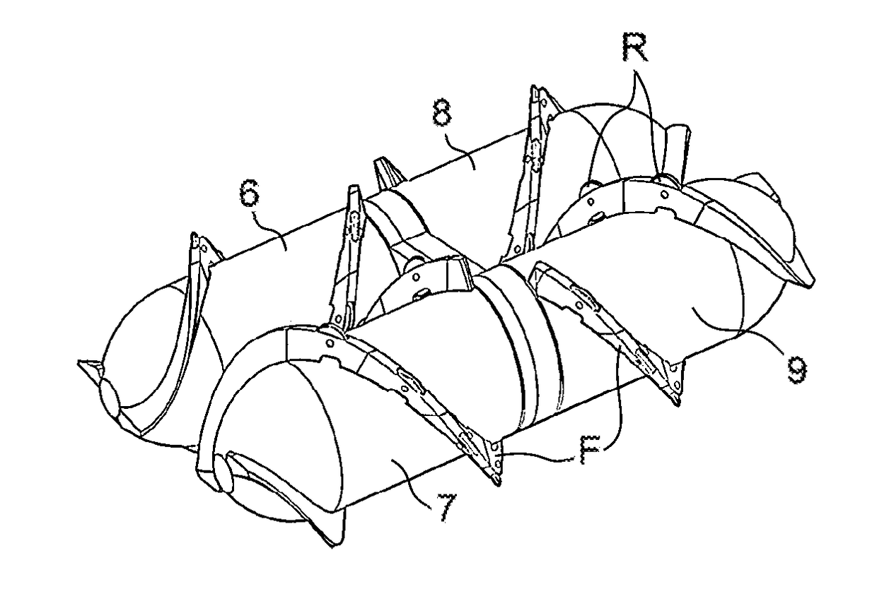
The invention is a mobile device that can inspect pipes in various environments. It is designed to be an all-terrain device that can advance regardless of the circumstances encountered in the pipes and still move forward if it is accidentally flipped onto its back. The device has a symmetrical shape that allows it to be moved indifferently on its front or back by propulsion elements.

Problems solved by technology

Moreover, in the event that the device is flipped over, for example as a result of the presence of an obstacle, the device can no longer continue to move forward and must be manually recovered.
These cleaning and recovery operations generate significant costs.
As a result of the design thereof with a central module positioned above the propulsion elements, said device does not tolerate being accidentally flipped over “onto its back”.

Method used


Image

  • Pipe-inspection device propelled by an archimedes screw
  • Pipe-inspection device propelled by an archimedes screw
  • Pipe-inspection device propelled by an archimedes screw

Examples


first embodiment

[0042]In a first embodiment shown in FIGS. 1 to 3, an electric motor and a power source are associated with each of the rotary drums and arranged inside the corresponding rotary drum.

[0043]In this first embodiment, each cylindrical portion of a pair of cylindrical portions of the body 10 forms a longitudinal recess 11, 12; 13, 14 designed to receive an electric motor 17, 18; 19, 20 capable of rotating the corresponding rotary drum and an electric power source 21a-21c, 22a-22c; 23a-23c, 24a-24c capable of powering the electric motor.

[0044]Each longitudinal recess 11, 12; 13, 14 of a pair is mounted inside a rotary drum 6, 7; 8, 9 of a pair of propulsion elements such that the compartment 15; 16 is arranged between the propulsion elements 2, 3; 4, 5 at the level of the median sagittal plane PS.

[0045]An electric motor and an electric power source are thus incorporated into each rotary drum, and the at least one sensor is arranged between the drums. Therefore, the device does not requir...

second embodiment

[0057]In a second embodiment shown in FIGS. 4 and 5, the electric motors and the power sources thereof are arranged behind a pair of propulsion elements. The motors are more specifically placed back-to-back and each allow one of the rotary drums of a pair of propulsion elements to be rotated.

[0058]In this second embodiment, the body 110 comprises a pair of cylindrical portions 50, 60, and the transverse junction portion 70 comprises a pair of transverse recesses, each provided in order to receive an electric motor 500, 600. Within the scope of this embodiment, the at least one electric power source is housed in the compartment 15, 16 that receives the at least one sensor. For example, FIG. 5 shows two batteries 151, 152, 161, 162 for powering each motor 500, 600. The at least one sensor can comprise one or more cameras housed in the compartment in a similar manner to that shown in FIG. 3 and described above.

[0059]Also in this second embodiment, the device 100 can include only a sing...


PUM


Abstract

A robotic device for inspecting a pipe includes at least one pair of propulsion elements each including a rotary drum, an outer surface of which has a screw thread. The device also includes a body associated with at least one pair of propulsion elements and in which are inserted sensor, at least one pair of electric motors each capable of rotating a rotary drum, and at least one pair of electric power sources each capable of powering an electric motor. The body is shaped such that a ventral portion and a dorsal portion of the device are symmetrical with one another relative to a median frontal plane of the device, thus allowing the device to move indistinctly on the belly or on the back.

Description

TECHNICAL HELD[0001]The field of the invention is that of robotic devices for inspecting pipes such as waste water and rain water pipes or industrial pipes. The invention more particularly relates to a device propelled by means of an Archimedes screw capable of moving inside pipes in the presence of water, sand, grease or sludge, and having the advantage of tolerating being accidentally flipped over.PRIOR ART[0002]Mobile mechatronic devices are used to move inside district or industrial network pipes in order to perform an inspection, in particular by taking photographs.[0003]The locomotive function of such devices is generally provided by wheels or tracks. However, in order to prevent situations in which such devices become blocked, the pipe must generally be cleaned out using a high-pressure jet before the passage of the device. Moreover, in the event that the device is flipped over, for example as a result of the presence of an obstacle, the device can no longer continue to move ...

Claims


Application Information

Patent Timeline
Patent Type & Authority Applications(United States)
IPC IPC(8): F16L55/32F16L55/40B63H1/12B63H19/08B63H21/17
CPCF16L55/32F16L55/40B63H1/12B63H19/08B63H21/17F16L2101/30B63H2001/125G21C17/017
Inventor SOUVESTRE, FLORENT
Owner COMMISSARIAT A LENERGIE ATOMIQUE ET AUX ENERGIES ALTERNATIVES
Learn More