
Quick connector

Active Publication Date: 2018-05-03
HYUNDAI MOTOR CO LTD +1
View PDF5 Cites 2 Cited by
  • Summary
  • Abstract
  • Description
  • Claims
  • Application Information

AI Technical Summary

Benefits of technology

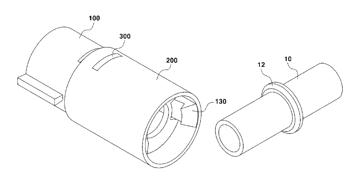
The present invention is a quick connector that has a connector body with locking members. These locking members are designed to be locked by a locking ring around a tube. The locking members can be easily engaged or disengaged with the locking ring by sliding a mounting guide on the connector body. This invention provides a more convenient and efficient way to connect and disconnect parts.

Problems solved by technology

However, when the connector is coupled to one end of the fuel filter, it is difficult to remove the connector from the fuel filter, which leads to inconvenience in repair and maintenance.

Method used


Image

  • Quick connector
  • Quick connector
  • Quick connector

Examples


Embodiment Construction

[0028]Hereinafter, reference will now be made in detail to various embodiments of the present disclosure, examples of which are illustrated in the accompanying drawings and described below. While the disclosure describes various example embodiments, it will be understood that the present description is not intended to limit the disclosure to those example embodiments. On the contrary, the disclosure is intended to cover not only the exemplary embodiments, but also various alternatives, modifications, equivalents and other embodiments, which may be included within the spirit and scope of the disclosure as defined by the appended claims.

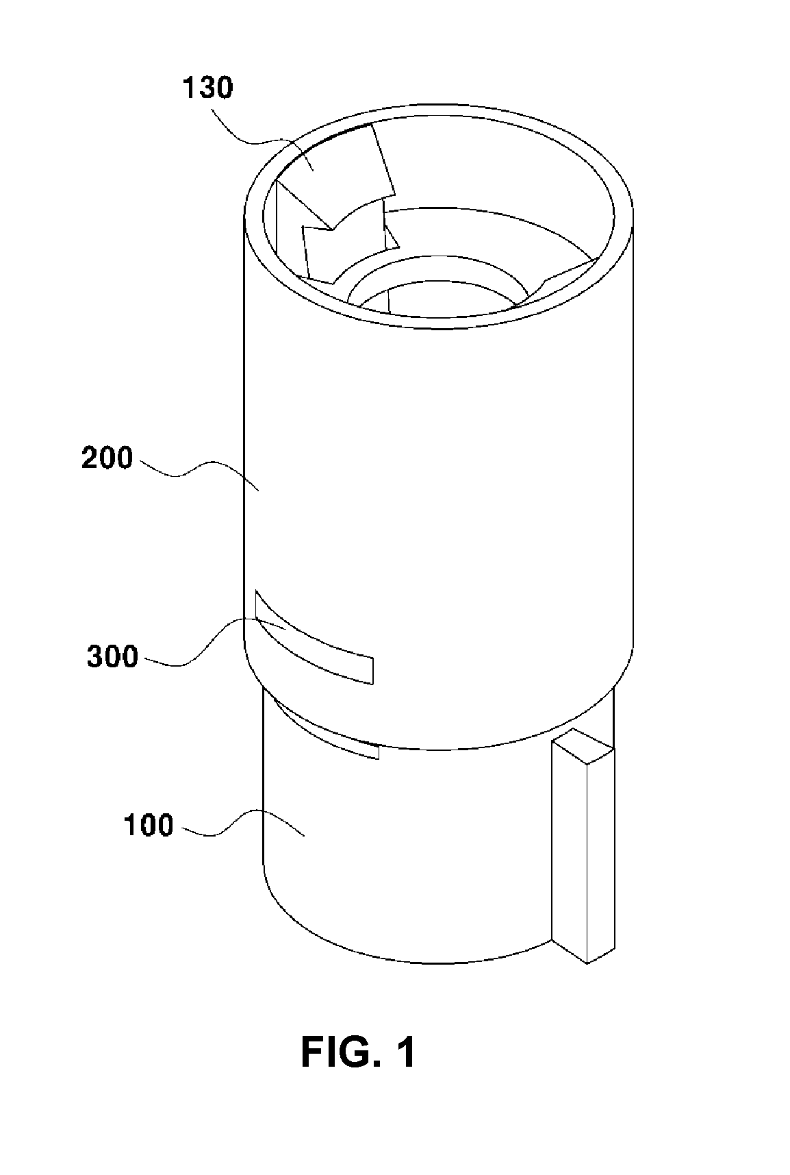
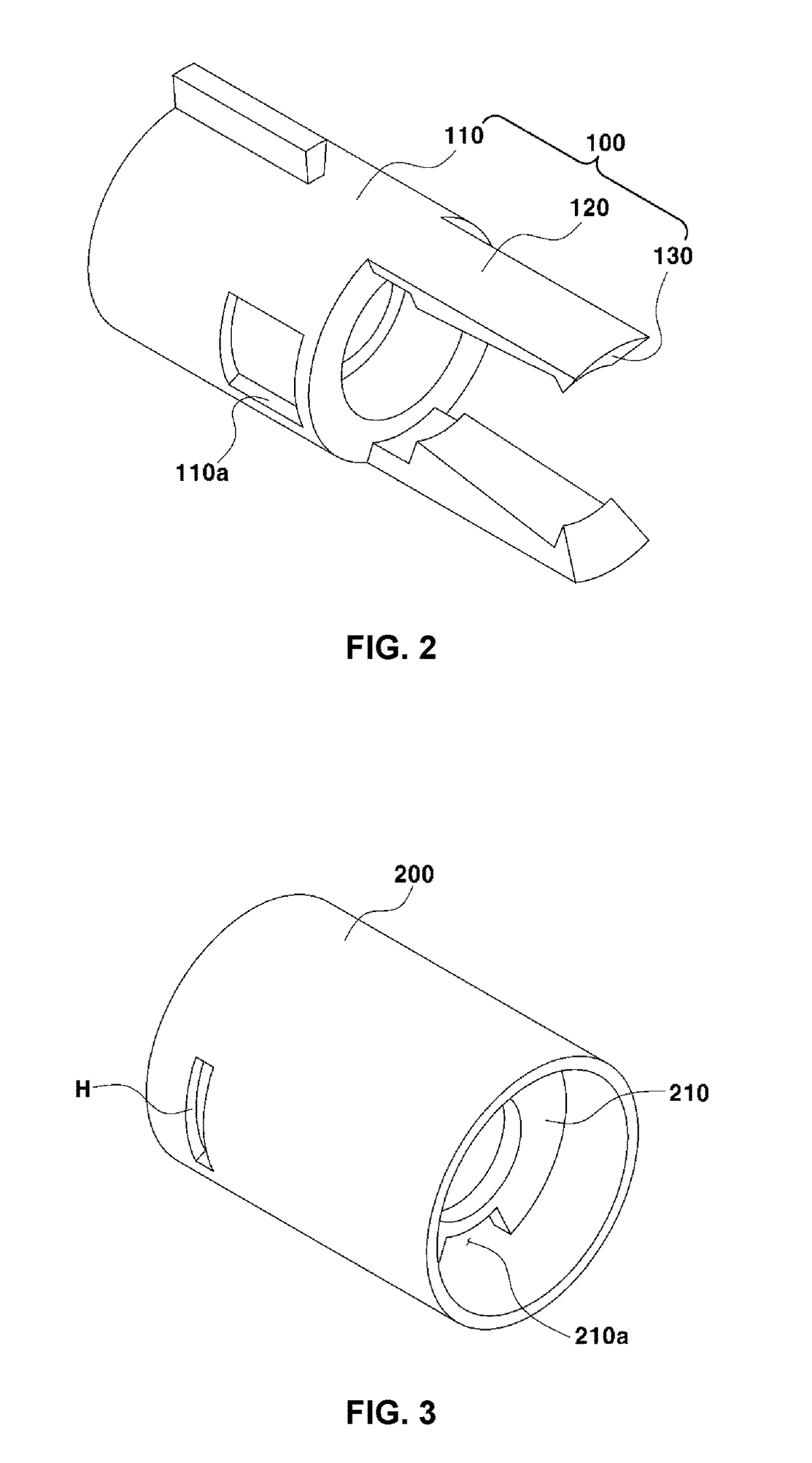
[0029]FIG. 1 is a view showing a quick connector according to an example embodiment of the present disclosure, FIG. 2 is a view showing a main body of the quick connector according to an example embodiment of the present disclosure, and FIG. 3 is a view showing a mounting guide of the quick connector according to an example embodiment of the present di...


PUM


Abstract

A quick connector is provided. The quick connector is configured to be coupled to a locking ring provided around an outer peripheral surface of a tube, through which fluid flows in or out. The quick connector includes a main body, which accommodates the tube therein and includes locking members, formed to be locked by the locking ring and being bent toward the locking ring, and a mounting guide coupled to the outer peripheral surface of the main body and accommodating the locking members therein. The mounting guide is configured to slide along the longitudinal axis of the main body so as to enable the locking members to be locked around the locking ring or to be released from the locked state.

Description

CROSS-REFERENCE TO RELATED APPLICATION[0001]This application claims under 35 U.S.C. § 119(a) the benefit of and priority to Korean Patent Application No. 10-2016-0144865 filed on Nov. 2, 2016, the entire contents of which are incorporated herein by reference.BACKGROUND(a) Technical Field[0002]The present disclosure relates to a quick connector. More particularly, it relates to a quick connector that is characterized by reducing manufacturing costs and improving engagement / disengagement performance.(b) Background Art[0003]In general, among various components of a vehicle, for example, a fuel supply device may be configured such that a fuel filter continuously delivers fuel, a pressure regulator maintains a uniform internal pressure in a fuel supply pipe (about 3.3 kg / cm2), excess fuel is returned to a fuel tank via a return pipe, and the fuel, which is maintained at a constant pressure, is sprayed into the engine via an injector.[0004]The fuel filter may be connected with a first con...

Claims


Application Information

Patent Timeline
IPC IPC(8): F16L37/12F16L37/14F16L37/133
CPCF16L37/122F16L37/142F16L37/133F02M37/0017F02M37/22F16L37/138F02M55/02F16L37/098F16L55/00F02M37/00
Inventor LEE, SEUNG YEUBJUNG, HEE JINCHO, YOUNG GUNHAN, SE JINJEONG, JIN HAKANG, JEONG WOOPARK, SO HYUNHAN, JI YOUN
Owner HYUNDAI MOTOR CO LTD
Learn More