
Air purifying apparatus

a technology of air purification apparatus and air filter, which is applied in the direction of lighting and heating apparatus, heating types, separation processes, etc., can solve the problems of inability to add or combine light emitting lamps according to user demands, inability to implement various requirements, and inability to direct separation and elimination of contaminants, so as to prevent the lowering of the performance of dust collecting apparatus or secondary contamination, improve the separation performance of sludge, and improve the convenience of use

Inactive Publication Date: 2018-04-26
LEE SEONG HUN
View PDF0 Cites 12 Cited by
  • Summary
  • Abstract
  • Description
  • Claims
  • Application Information

AI Technical Summary

Benefits of technology

The air purifying apparatus described in this patent has several benefits. First, it includes a feature that automatically removes sludge from the filter unit, which improves its convenience of use. Second, by continuously discharging sludge outside of the filter, it prevents damage to the filter and prevents secondary contamination. Third, the apparatus includes a sludge separation unit that improves the performance of the filter. Lastly, the air that passes through the filter passes through a photocatalytic purification unit, which improves the sterilizing performance of the air.

Problems solved by technology

However, according to the related art, sludge is continuously collected in the interior of the dust collecting apparatus when the dust collecting apparatus is used for a long time and a separate operation should be performed to processing the sludge, which is inconvenient.
However, according to the related art, only air purification due to a photocatalytic reaction is simply allowed and direct separation and elimination of contaminants is impossible, and in particular, it is impossible to add or combine a light emitting lamp according to a demand of the user, making it impossible to implement various requirements.

Method used


Image

  • Air purifying apparatus
  • Air purifying apparatus
  • Air purifying apparatus

Examples


second embodiment

Hereinafter, the present invention will be described.

[0119]The second embodiment of the present invention is the same as the first embodiment of the present invention except for the structure of the sludge processing unit, and thus the same structures are denoted by the same reference numerals and a description thereof will be omitted.

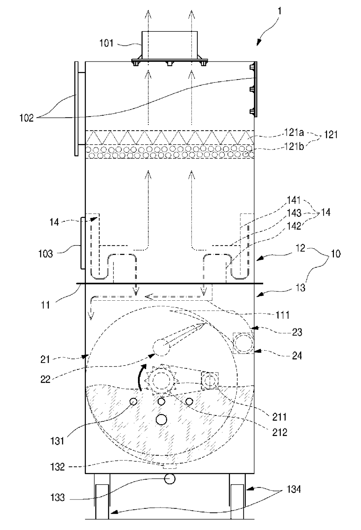
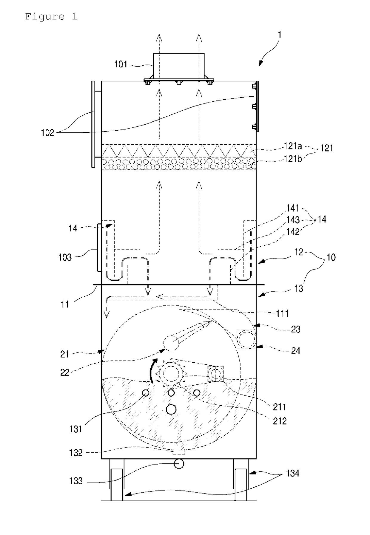
[0120]FIG. 7 is a side view illustrating a structure of a sludge processing unit according to a first embodiment of the present invention. FIG. 8 is a front view illustrating the structure of the sludge processing unit.

A drum 21 driven by a drum motor 211 is provided in the interior of a sludge processing unit 13 of the dust collecting apparatus 1 according to the second embodiment of the present invention. An ultraviolet lamp 131, a water supply pump 152, and a water discharge value 133 may be provided in the case 10.

[0121]Meanwhile, a sludge discharge unit 30 is provided in the sludge processing unit 13. The sludge discharge unit 30 may include a dru...


PUM

PropertyMeasurementUnit
bending angleaaaaaaaaaa
circumferenceaaaaaaaaaa
areaaaaaaaaaaa

Abstract

The present invention provides an air purifying apparatus that can continuously discharge sludge separated from suctioned contaminated air from a dust collecting apparatus to the outside, thereby improving convenience of use and air purifying performance, and can mix contaminated air with water, eliminate the sludge and contaminants in the air, and allow the eliminated sludge and contaminants to pass through a photocatalytic purifying unit and purify air using a photocatalytic reaction, thereby improving air purifying performance.

Description

TECHNICAL FIELD[0001]The present invention relates to an air purifying apparatus.BACKGROUND ART[0002]In general, an air purifying apparatus is an apparatus for eliminating contaminants such as floating particles in the air, germs, and toxic gases to maintain a cleanliness of an environmental space, and may purify air using various methods such as oxidation, reduction, decomposition, adsorption, filtering, electrical collection, and washing.[0003]In particular, the air purifying apparatus may include a dust collecting apparatus, and may be variously used in industrial fields, cattle sheds, workings, homes, offices, and restaurants.[0004]As an example of a dust collecting apparatus, Korean Patent No. 10-1296243 discloses an air purifying wet dust collecting apparatus in which air introduced from the outside is continuously cooled by circulating coolants and sludge and foreign substances are eliminated so that contaminated air can be cooled and the sludge in the air can be efficiently ...

Claims


Application Information

Patent Timeline
Patent Type & Authority Applications(United States)
IPC IPC(8): B01D47/06B01D50/00B01D53/86C02F11/12A61L9/20A61L9/00C02F11/127
CPCB01D47/06B01D50/006B01D53/86C02F11/127A61L9/205A61L9/00B01D2255/802B01D2255/20707C02F2103/18F24F13/00F24F13/28F24F8/20F24F8/117F24F8/22F24F8/108F24F8/30F24F8/192F24F8/10B01D53/14B01D53/18B01D2252/103B01D2258/06B01D2247/04B01D2247/106B01D2247/107A61L2/08A61L2/10B01D50/60
Inventor LEE, SEONG HUN
Owner LEE SEONG HUN
Learn More