
Predistortion system and method using a predistortion function

a predistortion and function technology, applied in the field of predistortion system and predistortion method, can solve the problems of non-optimal, respectively faulty, predistortion, and the system and method shown there though are not optimal for some applications, so as to reduce the computational complexity of the signal generator and remove the negative effects of non-linear distortion, the effect of high quality

Active Publication Date: 2018-04-12
ROHDE & SCHWARZ GMBH & CO KG
View PDF0 Cites 0 Cited by
  • Summary
  • Abstract
  • Description
  • Claims
  • Application Information

AI Technical Summary

Benefits of technology

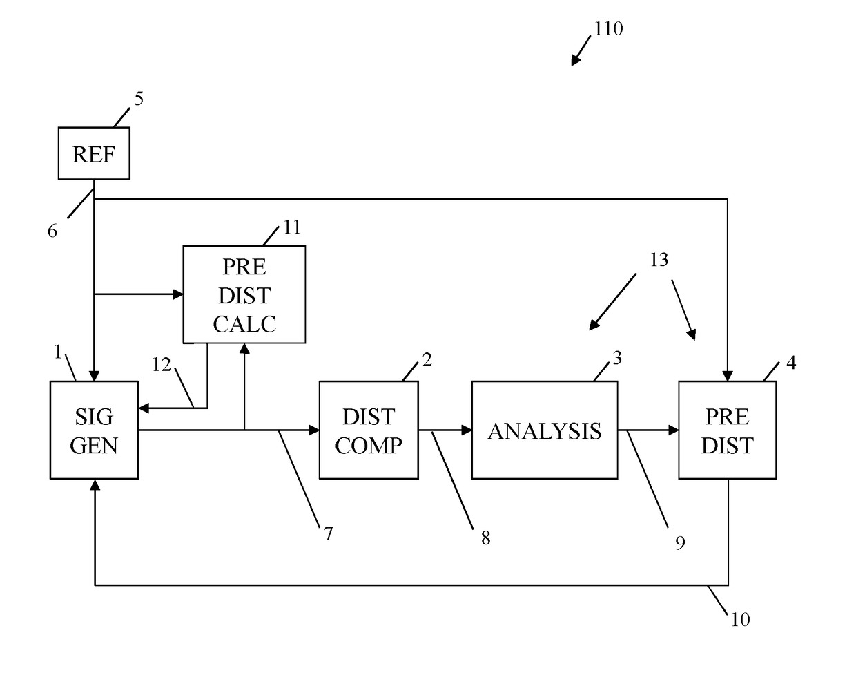
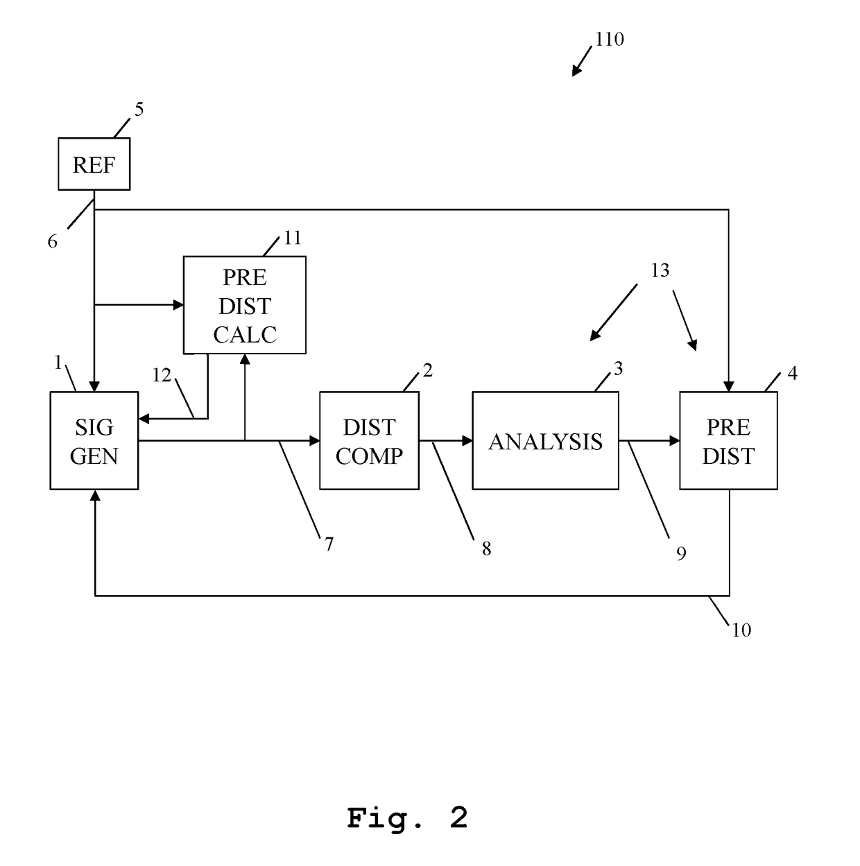
The invention is about a system for improving the quality of signals by using multiple reference signals and iterative adjustment. The system includes a signal generator, a distortion component, and an iterative predistortion device that works with a predistortion calculation device to determine a compensated signal. This compensated signal is then used as a reference signal for further reference signals. This ensures a high quality predistortion is available from the beginning on. The iterative predistortion device can analyze the signals in the frequency and time domains, and the predistortion calculation device can determine the predetshortion function as a transformation function. These forms of the invention simplify the process of improving signal quality and reduce complexity.

Problems solved by technology

In this context, due to the fact that in practice, there are no ideal components having a completely linear characteristic available, the performance of distorting components has to be optimized especially regarding linearity.
Nevertheless, the aforementioned document does not consider providing the reference signal not only for the purpose of generating a desired signal but also for the purpose of predistortion.
As a consequence of the lack of providing the reference signal also for predistortion, the total noise is the sum of the noise floor of the system and the respective noise components of each of the elements involved in predistortion, which leads to a non-optimal, respectively faulty, predistortion, and thus to a not perfectly optimized performance of the amplifier with special respect to linearity.
The system and method shown there though are not optimal for some applications, since it is not possible to judge if the predistortion determined iteratively is suitable for a different waveform.
Also, it is not possible to assure that the resulting predistortion filtering meets bandwidth conditions.
Moreover, it is difficult to foresee the performance of the predistortion device trained with baseline signals, when using real-world signals.

Method used


Image

  • Predistortion system and method using a predistortion function
  • Predistortion system and method using a predistortion function
  • Predistortion system and method using a predistortion function

Examples


Embodiment Construction

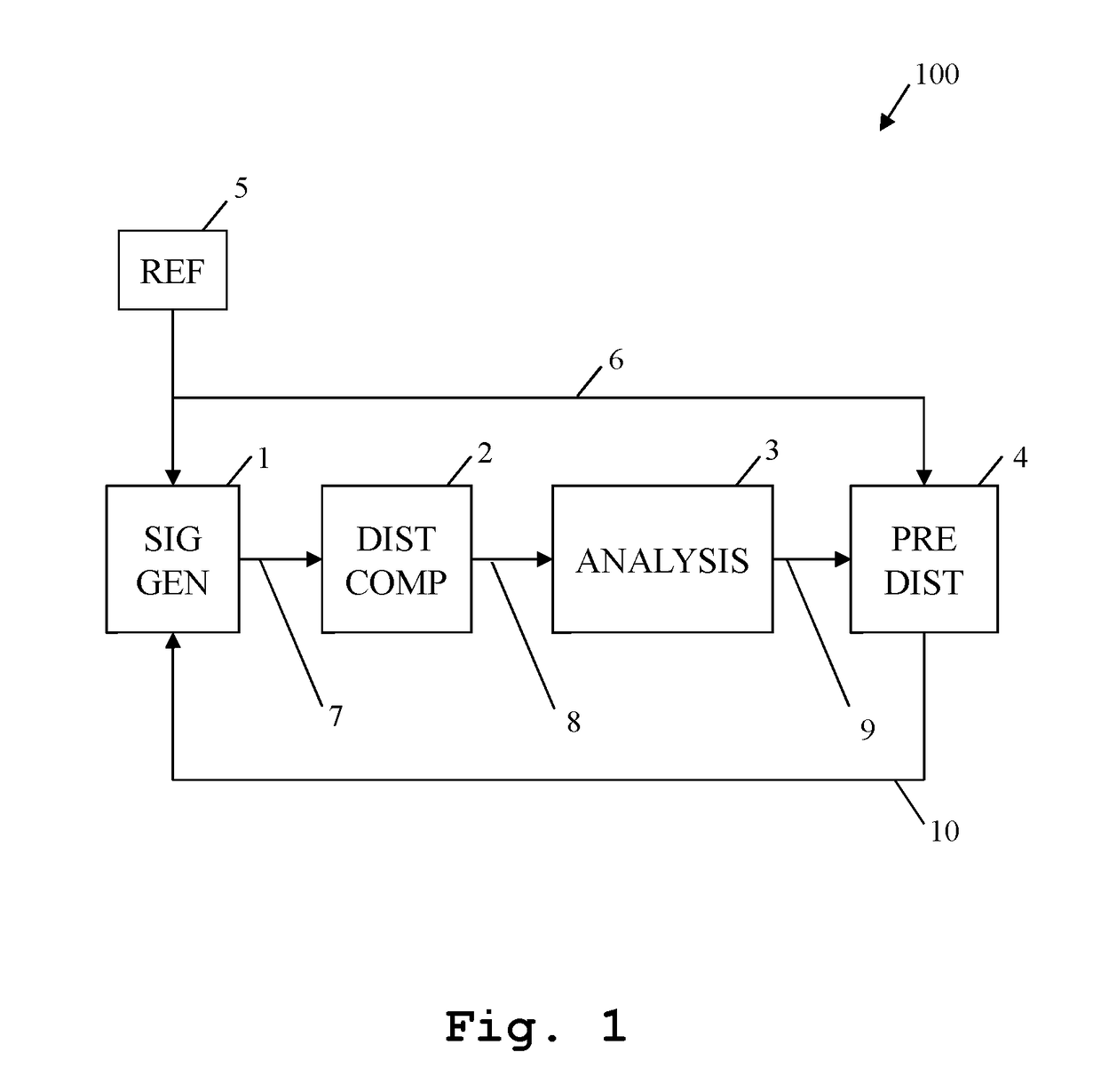
[0030]Now, from FIG. 1, an exemplary predistortion system 100 can be seen. A signal generator 1 generates a first signal 7 according to a reference signal 6, which is provided by reference signal source 5.

[0031]In the exemplary case according to FIG. 1, the reference signal source 5 is an external reference signal source. Alternatively, the reference signal source 5 may advantageously be part of the signal generator 1. Further advantageously, the reference signal source 5 may be implemented in hardware or software or a combination thereof. In addition to this, the reference signal 6 may be a fixed signal or a user-defined signal of any desired waveform.

[0032]Then, the first signal 7 is passed to a distorting component 2, which distorts the first signal 7 and outputs a corresponding second signal 8. Advantageously, the distorting component 2 is an amplifier.

[0033]Furthermore, an analyzing device 3 for frequency and / or time domain analysis, preferably a spectrum analyzer or an oscillo...


PUM


Abstract

A predistortion system for correcting a distortion of a distorting component is provided. It comprises a signal generator, adapted to generate a first signal based upon a reference signal, the distorting component, adapted to generate a second signal, based upon the first signal, and an iterative predistortion device, adapted to determine a compensated signal based upon the second signal and the reference signal. The signal generator is adapted to use the compensated signal as reference signal in further iterations after a first iteration. The predistortion system moreover comprises a predistortion calculation device, adapted to determine a predistortion function based upon the reference signal and the first signal. The signal generator is then adapted to generate the first signal based upon the predistortion function for further reference signals.

Description

PRIORITY[0001]This application claims priority of the European patent application EP 16 192 718.1 filed on Oct. 7, 2016, and U.S. Provisional Application No. 62 / 453,828, filed on Feb. 2, 2017, the entire contents of which are incorporated by reference herein.FIELD OF THE INVENTION[0002]The invention relates to a predistortion system and a predistortion method for optimizing the performance of distorting components.BACKGROUND OF THE INVENTION[0003]Typically, with special respect to communication applications, a linear behavior of the employed components, especially of amplifiers, is not only desired but even necessary in order to ensure the avoidance of nonlinear distortion, and thus the prevention of an undesirable interference spectrum. In this context, due to the fact that in practice, there are no ideal components having a completely linear characteristic available, the performance of distorting components has to be optimized especially regarding linearity.[0004]WO 99 / 05784 A1 di...

Claims


Application Information

Patent Timeline
IPC IPC(8): H04B1/04
CPCH04B2001/0425H04B1/0475H03F1/3247H03F1/3276H03F1/3282H03F3/189H03F3/245H03F3/19H03F2201/3215H04B1/04
Inventor WEISS, MARTIN
Owner ROHDE & SCHWARZ GMBH & CO KG
Learn More