
Ventilating and illuminating apparatus

a technology of ventilating and illuminating devices, which is applied in the direction of lighting and heating devices, ventilation systems, heating types, etc., can solve the problems of unaesthetic appearance, complicated design, and difficulty in installing, maintaining or replacing the illuminating device of the apparatus, so as to facilitate the execution of regular maintenance and reduce installation time and materials

Active Publication Date: 2018-03-22
DELTA ELECTRONICS INC
View PDF12 Cites 4 Cited by
  • Summary
  • Abstract
  • Description
  • Claims
  • Application Information

AI Technical Summary

Benefits of technology

The present invention is a ventilating and illuminating apparatus with a detachable illuminating device. The detachable illuminating device is fastened by modular parts, which saves time and materials in installation and makes maintenance easier. It is designed to be easily maintained and replaced, and is waterproof to prevent moisture from affecting the lighting. The apparatus also has modular parts that allow for easy customization and replacement.

Problems solved by technology

After combining the conventional ventilating fan and the conventional illustrating device simply, the conventional ventilating and illuminating apparatus generally has a bulky, unaesthetic appearance and employ a complicated design for integrating the ventilating and illuminating functions.
Furthermore, the combined apparatus seems difficult to install, maintain or replace the illuminating device without disassembling the relative ventilating fan.
When the components of the ventilating and illuminating apparatus can fail to be arranged efficiently, the ventilating fan can fail to cool the lighting device, and the illuminating device combined with the ventilating fan can be employed at high temperature and high humidity.
In the above operating condition, it is easy to damage the illuminating device.
Furthermore, comparing with the ventilating fan, the illuminating device need spare parts and maintenance.
However, it always takes a lot of time to maintain or replace the illuminating device from the entire ventilating and illuminating apparatus.

Method used


Image

  • Ventilating and illuminating apparatus
  • Ventilating and illuminating apparatus
  • Ventilating and illuminating apparatus

Examples


Embodiment Construction

[0018]The present invention will now be described more specifically with reference to the following embodiments. It is to be noted that the following descriptions of preferred embodiments of this invention are presented herein for purpose of illustration and description only. It is not intended to be exhaustive or to be limited to the precise form disclosed.

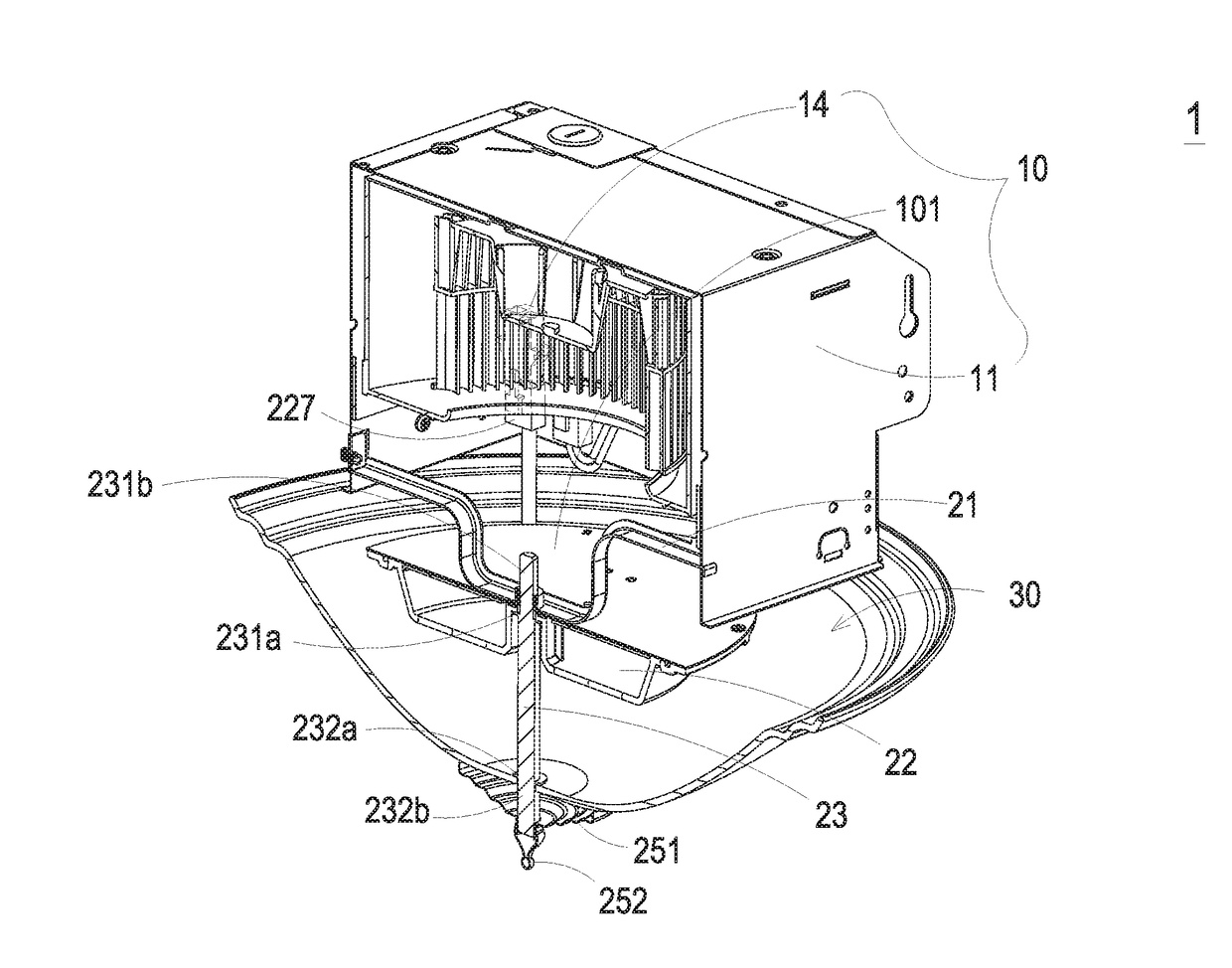
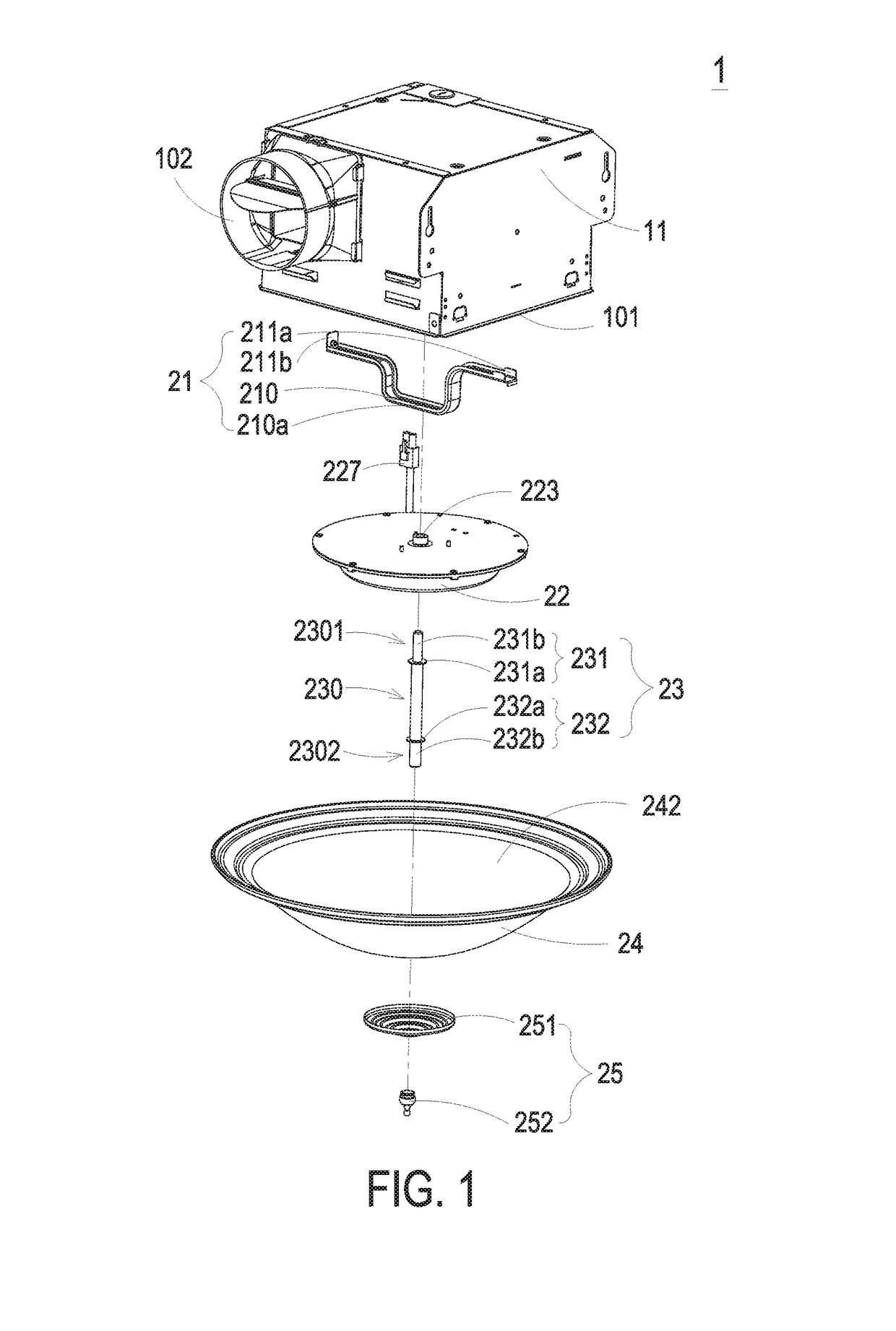
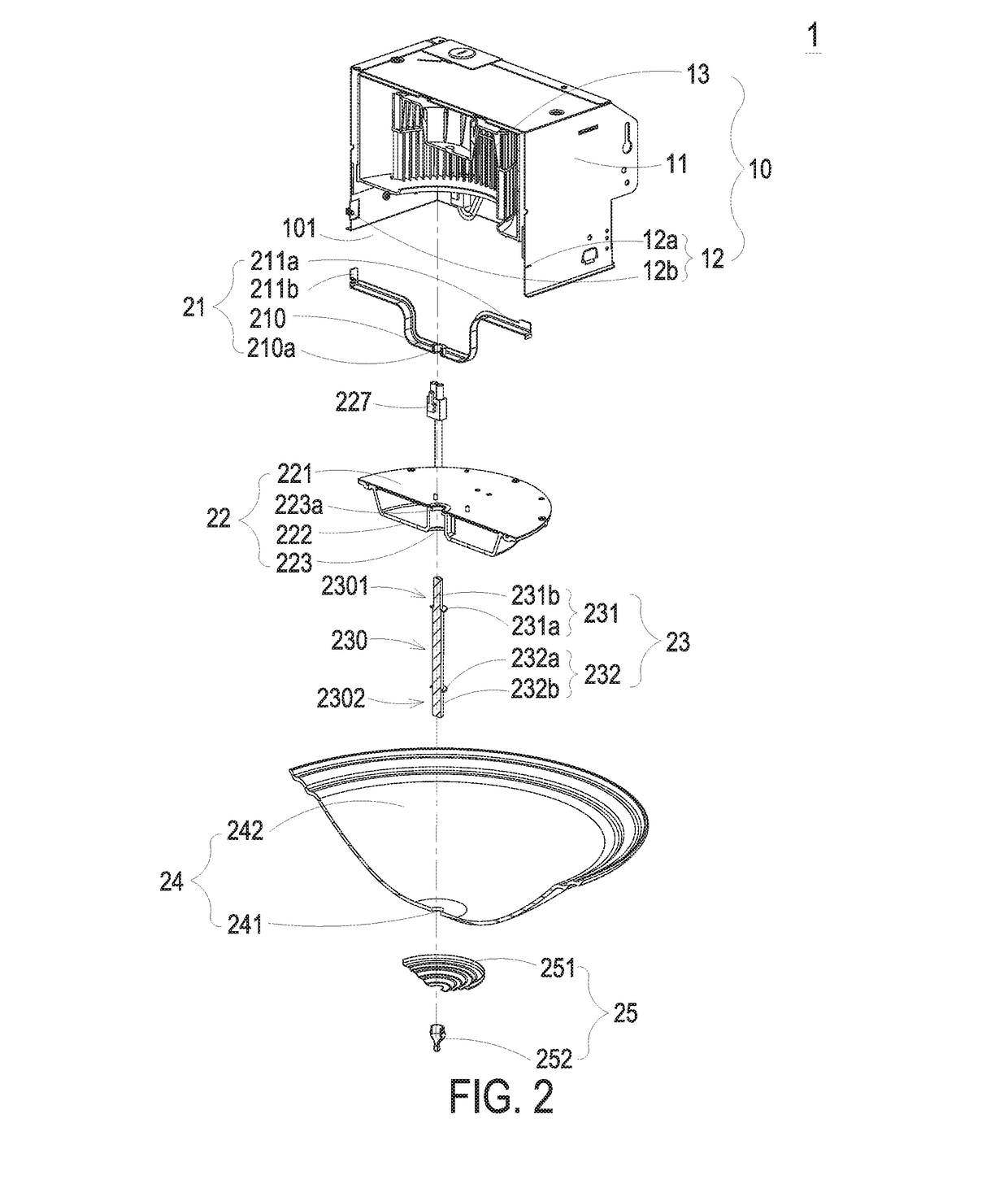
[0019]FIG. 1 is an exploded view illustrating a ventilating and illuminating apparatus according to a first preferred embodiment of the present invention. FIG. 2 is a sectional view of FIG. 1. As shown in FIGS. 1 and 2, the ventilating and illuminating apparatus 1 includes a ventilating fan 10, a connecting frame 21, an illuminating device 22, a connecting shaft 23, a lampshade 24, and a fixing element 25.

[0020]The ventilating fan 10 includes a housing 11, an inhaling opening 101, an exhausting opening 102 and a fan wheel 13, wherein the fan wheel 13 is rotated to create a flow of air from the inhaling opening 101 and out of the ...


PUM


Abstract

The present invention provides a ventilating and illuminating apparatus. The ventilating and illuminating apparatus includes a ventilating fan, a connecting frame, an illuminating device and a connecting shaft. The ventilating fan has a housing. The connecting frame is connected to the housing and has a mounting portion and a fastening hole. The fastening hole is disposed on the mounting portion. The illuminating device has an illuminating element and a through hole. The connecting shaft partially passes through the through hole of the illuminating device and the fastening hole of the connecting frame and is mounted on the mounting portion of the connecting frame, so as to fasten the illuminating device on the mounting portion of the connecting frame.

Description

FIELD OF THE INVENTION[0001]The present invention relates to a ventilating and illuminating apparatus, and more particularly to a ventilating and illuminating apparatus having a detachable illuminating device.BACKGROUND OF THE INVENTION[0002]With the increasing requests of indoor environmental quality (IEQ), ventilating fans are usually provided and installed into the ceiling. Furthermore, illustrating devices are usually installed on the ceiling. For saving the installation space, a conventional ventilating and illuminating apparatus can combine elements of a conventional ventilating fan with an illuminating device for controlling the indoor air quality and providing quiescent light at the same time. After combining the conventional ventilating fan and the conventional illustrating device simply, the conventional ventilating and illuminating apparatus generally has a bulky, unaesthetic appearance and employ a complicated design for integrating the ventilating and illuminating funct...

Claims


Application Information

Patent Timeline
Patent Type & Authority Applications(United States)
IPC IPC(8): F21V33/00F21V31/00F21S8/04F21V17/12F21V1/14F24F7/007
CPCF21V33/0096F21V31/005F24F7/007F21V17/12F21V1/146F21S8/04F24F3/056
Inventor TSAI, CHIA-YULIN, WEN-HSIANG
Owner DELTA ELECTRONICS INC
Learn More