
Coordinated Water Environment Mobile Robots

a robot and water environment technology, applied in the direction of pipe laying and repair, underwater equipment, borehole/well accessories, etc., can solve the problems of difficult stabilization of the rov, difficult robotic manipulation of an inspection tool, etc., and achieve the effect of improving the stability of the rov

Active Publication Date: 2018-03-22
SAUDI ARABIAN OIL CO
View PDF0 Cites 7 Cited by
  • Summary
  • Abstract
  • Description
  • Claims
  • Application Information

AI Technical Summary

Benefits of technology

The invention is a two-part, selectively dockable robotic system that provides counterbalanced stabilization during performance of an underwater target structure. The system includes a first underwater robotic vehicle that surrounds the target structure and a second underwater robotic vehicle that can be oriented opposite the first vehicle. The first vehicle can selectively couple with the target structure using docking mechanisms, while the second vehicle exerts a force in a different direction to counteract the first force. The system also includes a tool, such as a cleaning tool or a robotic arm, that can be supported by either the first or second vehicle. The system can be used in various underwater applications such as inspection, repair, and cleaning.

Problems solved by technology

Underwater inspection operations can be a complicated task for a robotic system, especially when the task is performed while floating in water, for example, at a midpoint of the water column.
Robotic manipulation of an inspection tool, such as an inspection arm, can be difficult as reaction forces from the inspected surface can push a remotely operated vehicle (“ROV”) backward and disturb its stability.
Similarly, performing marine life cleaning on an underwater pipe or pipeline, e.g., using a water jet, will create a strong push back making it difficult to stabilize the ROV.

Method used


Image

  • Coordinated Water Environment Mobile Robots
  • Coordinated Water Environment Mobile Robots
  • Coordinated Water Environment Mobile Robots

Examples


Embodiment Construction

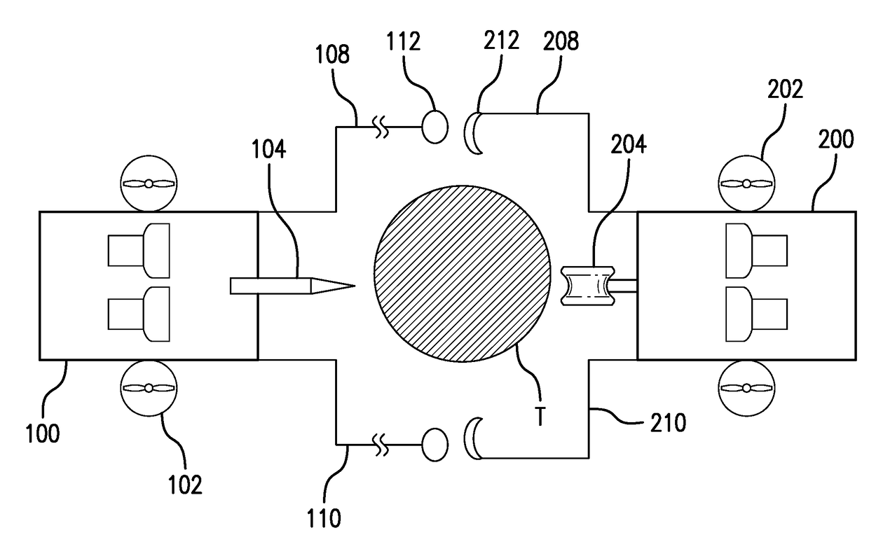
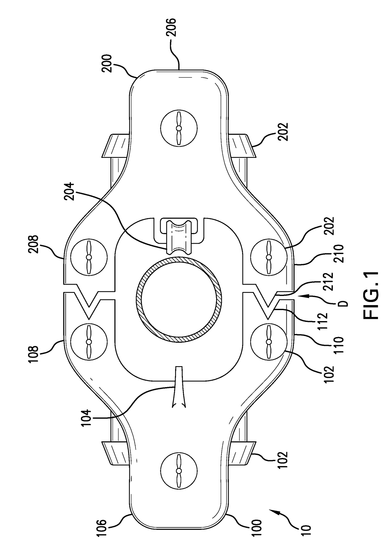
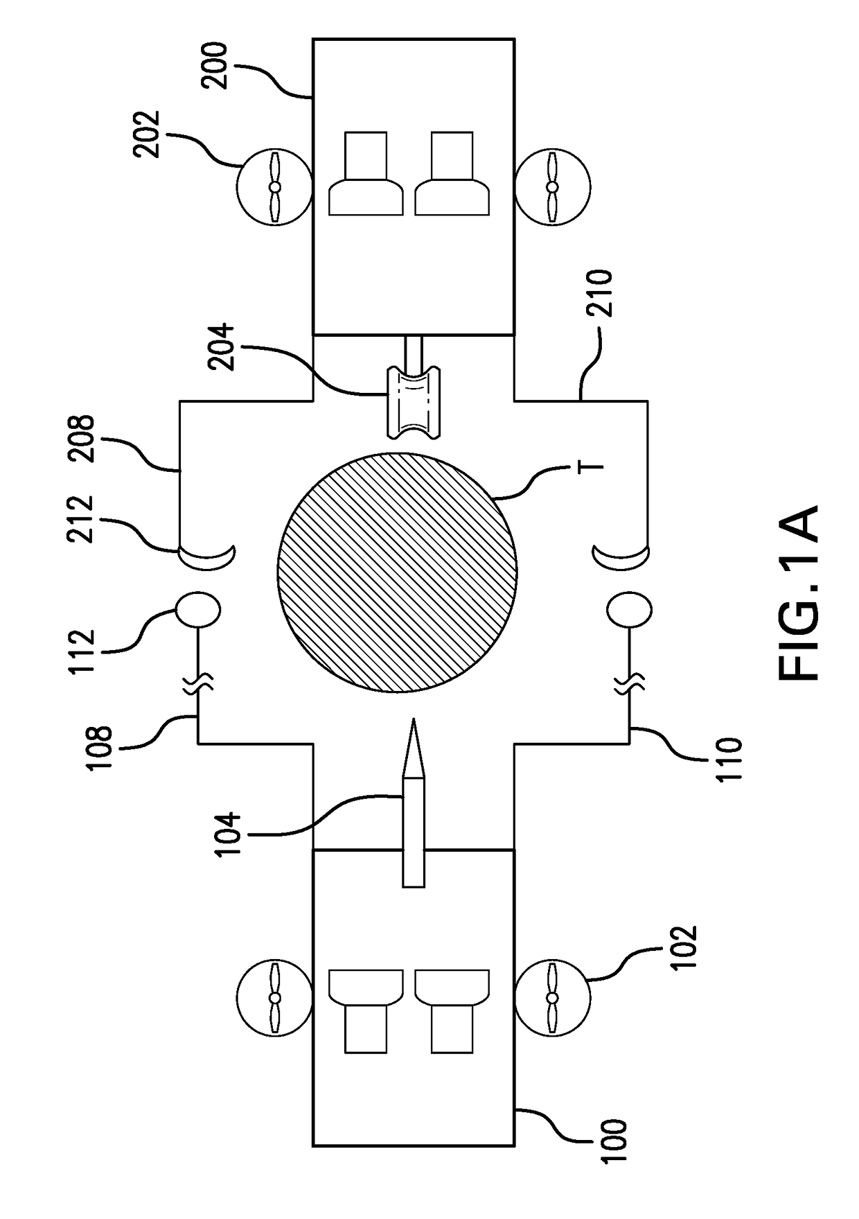
[0026]Referring to FIG. 1, a two part, selectively dockable robotic system 10 is provided. The robotic system 10 provides counterbalanced stabilization during performance of an operation (e.g., inspection, testing, cleaning, maintenance, construction, and repair) on an underwater target structure (e.g., pipe, cable, rig structure). The robotic system 10 includes first and second underwater robots 100, 200. The first and second underwater robots 100, 200 are controlled by a controller which is configured to coordinate their movements so that they cooperate and together improve the efficiency of various underwater tasks, as discussed in more detail below.

[0027]The first underwater robot 100 includes various thrusters 102 for maneuvering the robot 100 into position with respect to the target structure T. Once the robot 100 is in position, the thrusters 102 can be used to help maintain the position of the robot 100 and also translationally move the robot 100 along the target structure T...


PUM

PropertyMeasurementUnit
forceaaaaaaaaaa
stabilityaaaaaaaaaa
speedaaaaaaaaaa

Abstract

A two-part, selectively dockable robotic system having counterbalanced stabilization during performance of an operation on an underwater target structure is provided. The robotic system includes a first underwater robotic vehicle that is sized and shaped to at least partially surround the underwater target structure. A second underwater robotic vehicle is sized and shaped to at least partially surround the underwater target structure and selectively dock with the first underwater robotic vehicle. The first and second robotic vehicles include complimentary docking mechanisms that permit the vehicles to selectively couple to each other with the underwater target structure disposed at least partially therebetween. One robot includes a tool that can act upon the target structure and the other robot includes a stabilization module that can act upon the target structure in an opposite manner in order to counterbalance the force of the tool.

Description

CROSS-REFERENCE TO RELATED APPLICATIONS[0001]This application claims priority under 35 U.S.C. §119 to U.S. Provisional Application Ser. No. 62 / 397,175, filed Sep. 20, 2016, which is hereby incorporated by reference as if set forth in its entirety herein.FIELD OF THE INVENTION[0002]Systems, methods and devices for performing inspection and other tasks on underwater assets including underwater pipelines and structures are provided that include or utilize at least first and second robots that are configured to cooperate with one another in support of an operation on a target pipeline or other structure.BACKGROUND OF THE INVENTION[0003]Underwater inspection operations can be a complicated task for a robotic system, especially when the task is performed while floating in water, for example, at a midpoint of the water column. Robotic manipulation of an inspection tool, such as an inspection arm, can be difficult as reaction forces from the inspected surface can push a remotely operated ve...

Claims


Application Information

Patent Timeline
Patent Type & Authority Applications(United States)
IPC IPC(8): E21B41/04B63C11/42B25J9/00
CPCE21B41/04B63C11/42B62D57/00B63G8/00B25J9/0009B08B3/024B08B9/023B63C11/52B63G2008/002F16L1/265F16L1/26G01N2291/2634B23K31/125B63G8/001B63G8/14B63G2008/005B63H19/08G01N29/225G01N2291/0234B08B1/12B25J11/00B25J15/0019B25J19/0075B08B1/00B25J15/0009B25J15/0028B63G8/42B63G2008/008F16H19/08F16H35/18F16H2019/085F16L55/00G01B17/02G01N29/04G01N2291/02854G01N2291/2675
Inventor OUTA, ALIABDELLATIF, FADLPATEL, SAHEJAD
Owner SAUDI ARABIAN OIL CO
Learn More