
Simulation method for developing a production process

a production process and simulation method technology, applied in the direction of additive manufacturing processes, program control, instruments, etc., can solve the problems of difficult to assess deviations, limit further development, and entail considerable time and expense for empirical determination, so as to achieve rapid and reliable development of additive production of components

Inactive Publication Date: 2018-03-15
MTU AERO ENGINES GMBH
View PDF0 Cites 9 Cited by
  • Summary
  • Abstract
  • Description
  • Claims
  • Application Information

AI Technical Summary

Benefits of technology

The present invention provides a technique for quickly and reliably developing an additive production of a component. The simulation method enables an integrated assessment of the production chain, taking into consideration a multiscale, interdisciplinary physical approach. This approach helps in developing a production process or process chain with potential useful parameters, parameters windows, and the like. The method also allows sensitivity and deviation assessment, reducing the outlay for process development and sensitivity studies. The optimized process parameters are fed back to the first phase of the method, making it possible to optimize the process development and component manufacturing. The viewing plane in the method is greater, making it faster to run the simulation through. This invention can be beneficial in improving the quality and efficiency of additive manufacturing.

Problems solved by technology

However, the empirical determination entails considerable time and expense.
When individual parameters deviate in one step of the production chain, it is not possible to quantify the effects of these deviations on subsequent steps.
This makes it difficult to assess deviations and limits further developments, such as the use of alternative materials and other process parameters.

Method used


Image

  • Simulation method for developing a production process
  • Simulation method for developing a production process
  • Simulation method for developing a production process

Examples


Embodiment Construction

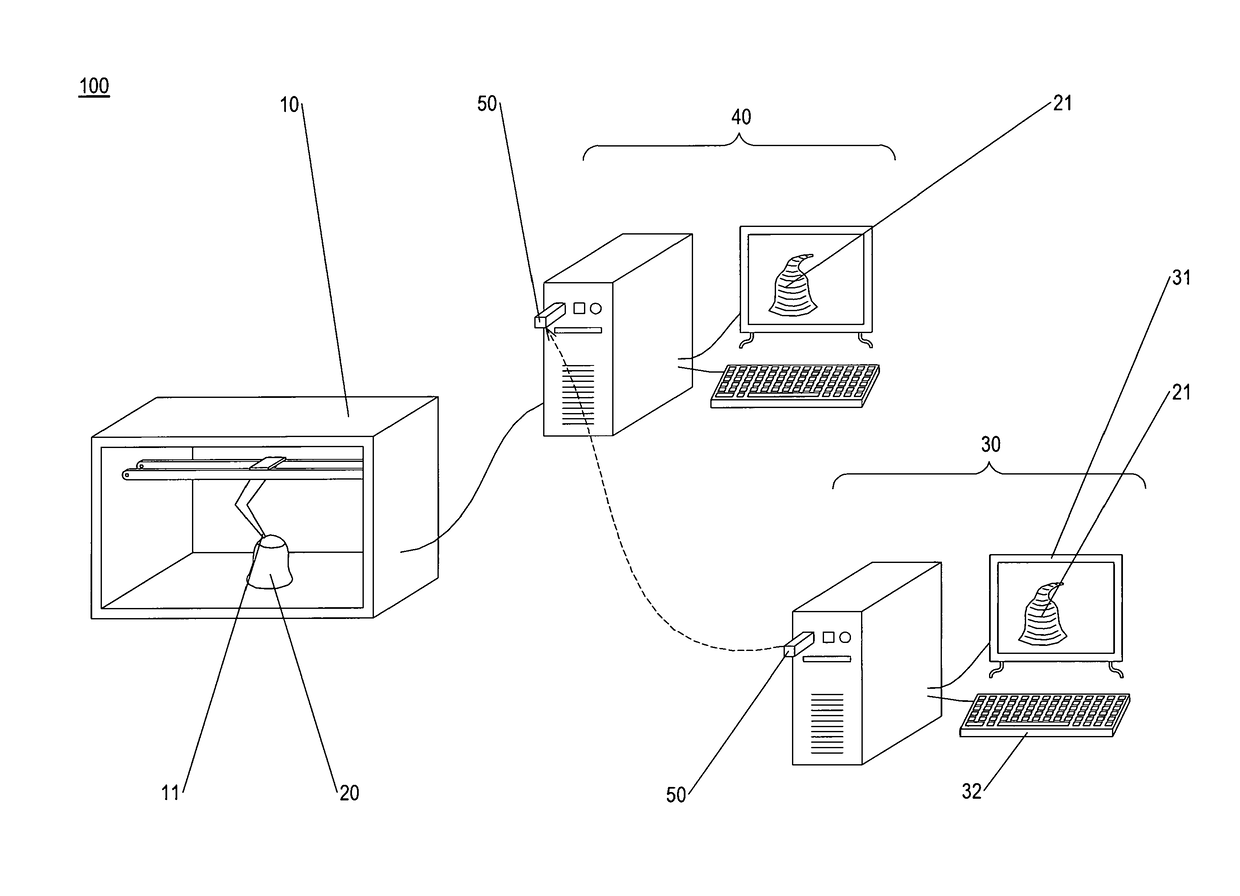
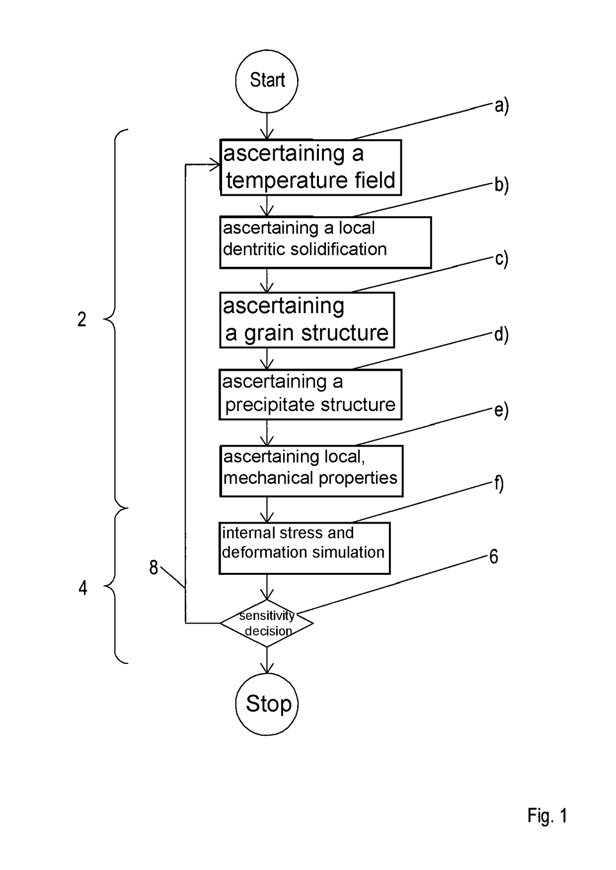
[0033]FIG. 1 shows method 1 according to the present invention on the basis of a greatly simplified flow chart. It is intended that a component be additively manufactured layer by layer by melting on powder material using a radiation source, and that the melted-on powder material be subsequently solidified. The powder material is metal-based, for example, and a laser is used as a radiation source. It is intended that a production process for additively manufacturing the component with optimal strength properties be developed prior to the physical manufacture of the component. To this end, specific properties of a material are ascertained in a first phase 2 of the method as a function of process parameters, independently of a component geometry. In a second phase 4 of the method, a component is then built up using this material, taking into account the process parameters and the specific properties.

[0034]The first phase of the method includes a multiscale, physically based modeling. ...


PUM

PropertyMeasurementUnit
temperatureaaaaaaaaaa
grain structureaaaaaaaaaa
precipitate structureaaaaaaaaaa

Abstract

A method for developing a production process where a component is built up layer by layer by melting on powder material using a radiation source, and the melted-on powder material is subsequently solidified; in a first phase of the method, material-specific properties of a material being ascertained as a function of process parameters in a multiscale, physically based simulation chain independently of a component geometry; and, in a second phase of the method, taking into account the process parameters and the material-specific properties, an additive build-up of the component using this material being simulated which ensures minimal distortions and internal stresses. Also described is an installation for the generative production of components that includes a processing unit that is adapted for implementing a method for developing a production process.

Description

[0001]The present invention relates to a method for developing a production process where a component is built up layer by layer by using a radiation source to melt on powder material, and the melted-on powder material is subsequently solidified. The present invention also relates to an installation for additively manufacturing components.BACKGROUND[0002]Complex components can be directly created from a computer model using additive production processes, also known as “rapid prototyping” or “additive manufacturing.” A widely used additive production process is beam melting. In beam melting, the component is built up layer by layer by melting on powder material using a radiation source and by subsequently solidifying the melted-on powder material. The powder material is generally metal-based, and a laser or an electron beam is used as a radiation source.[0003]Interactions between chemical compositions of the powder material, manufacturing parameters and final properties of the partic...

Claims


Application Information

Patent Timeline
Patent Type & Authority Applications(United States)
IPC IPC(8): B23K26/342G06F17/50G05B19/4099B33Y30/00B33Y50/02B33Y10/00B23K26/70
CPCB23K26/342G06F17/5009G05B19/4099B33Y30/00B33Y50/02B33Y10/00B23K26/702G06F2217/02G05B2219/35134G05B2219/49004B29C64/153G06F30/20G06F2111/20B22F10/80
Inventor GOEHLER, THOMASMAIWALD-IMMER, TOBIASFISCHERSWORRING-BUNK, ANDREAS
Owner MTU AERO ENGINES GMBH
Learn More