Rolling Motorcycle Stand

Inactive Publication Date: 2018-03-01
OLSON RICHARD ANTHONY
View PDF42 Cites 0 Cited by
  • Summary
  • Abstract
  • Description
  • Claims
  • Application Information

AI Technical Summary

Benefits of technology

The present invention is a rolling motorcycle stand that allows for easy movement of a parked motorcycle. It consists of two lift arms with rotating castor wheels and a lift assembly with a rotating castor wheel. The lift arms can be adjusted to different motorcycling needs and are attached to a base assembly for easy use. The stand is designed to allow for efficient use of space in garages and can also be used for other vehicles. Its unique design allows for side-to-side shifting of the motorcycle to increase space availability. Overall, the stand provides a convenient and easy way to move motorcycles and other vehicles around.

Problems solved by technology

Typically, garages and other similar parking structures, particularly where the structure is older, have limited accessible room for vehicles.
That is, garages and other structures often have a more limited area where vehicles can actually be placed within the garage or similar structure when the vehicle is driven into the structure due to the location and size of the garage door(s).
For example, in the case of a one car garage, if a motorcycle is driven into the garage and parked, there often is not sufficient space to also park a car or truck in the garage because it is difficult, when driving the motorcycle into the garage, to park the motorcycle very close to the wall of the garage or similar structure.
However, since such stands are not mobile, they do not address the problem at issue, which is the parking of the motorcycle interfering with the parking of other vehicles in the structure.
While these stands would indirectly allow a motorcycle to steer and turn to move the motorcycle to one side or another while it rolls forward or backward, the stands, due to their fixed wheel, do not allow the stand to be shifted laterally alone (that is, perpendicular to the direction the motorcycle is pointed in).
As such, these stands also do not address the issue at hand.

Method used


Image

  • Rolling Motorcycle Stand
  • Rolling Motorcycle Stand
  • Rolling Motorcycle Stand

Examples


Embodiment Construction

)

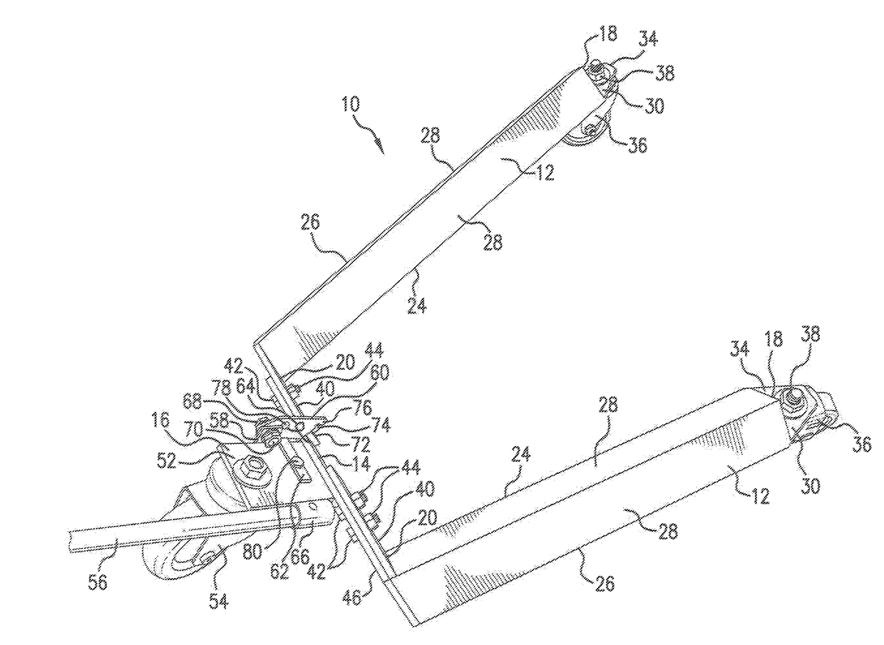
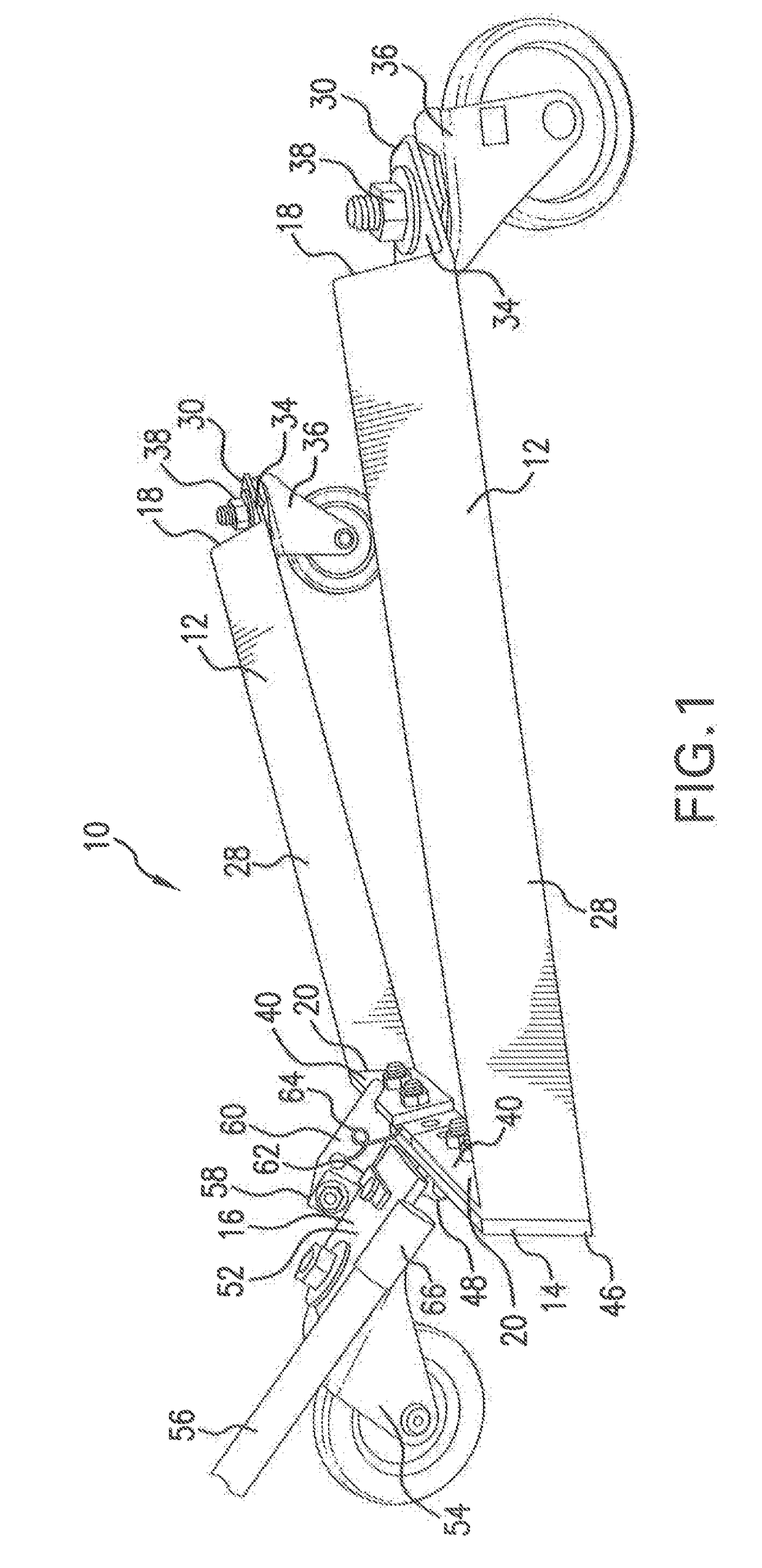
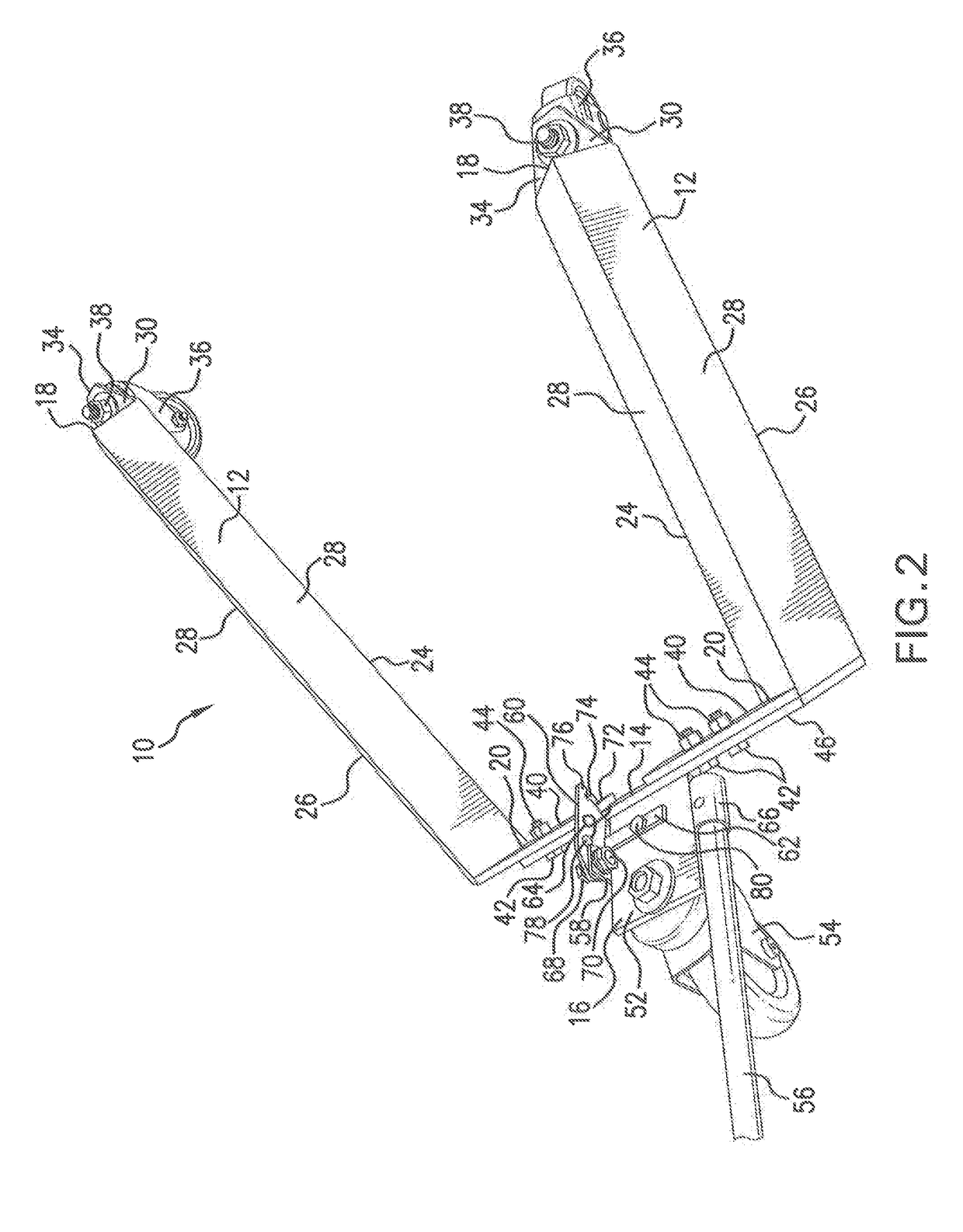
[0018]Referring now to FIGS. 1 through 7, a preferred embodiment of the rolling motorcycle stand 10 is shown. The motorcycle stand 10 of the present invention comprises two lift arms 12, a base assembly 14, and a lift assembly 16.

[0019]The lift arms 12 of the motorcycle stand 10 extend from the base assembly 14 at angle slightly less than ninety (90) degrees, such that at the outer ends 18 of the lift arms 12 are further apart than the inner ends 20 of the lift arms 12 nearest the base assembly 14. The angled configuration of the lift arms 12 allows the motorcycle stand 10 to be used with a variety of wheel sizes and also makes it easier to roll the motorcycle stand 10 (in its lowered configuration as best shown in FIGS. 1 through 5) beneath a wheel 22 of a motorcycle or similar vehicle. While any angle between the lift arms 12 and the base assembly14 may be selected in accordance with the range of wheel sizes that the motorcycle stand 10 will be used with, in one embodiment of the...


PUM


Abstract

A lightweight yet strong and easy to use, rolling motorcycle stand is provided. The preferred embodiment of the rolling motorcycle stand includes a two lift arms, each with one rotating castor wheel, and a lift assembly, which also includes a rotating castor wheel, connected to the lift arms by a hinge. The stand can be shifted from its lowered configuration to its raised configuration by operating a lever on the lift assembly. The rolling motorcycle stand allows a user to laterally shift or move a parked motorcycle or other motor vehicle.

Description

BACKGROUND OF THE INVENTION[0001]The invention disclosed herein relates to a rolling motorcycle stand and, more specifically, a rolling motorcycle stand that may be easily moved around on rollers. The present invention provides a rolling motorcycle stand which may be used to allow a user to laterally shift or move a parked motorcycle, thereby allowing for the more efficient use of space.[0002]It is not unusual for a motorcycle to share a garage, or similar parking area, with other vehicles, yard equipment, tools, and many other things that individuals store in garages and similar structures. Typically, garages and other similar parking structures, particularly where the structure is older, have limited accessible room for vehicles. That is, garages and other structures often have a more limited area where vehicles can actually be placed within the garage or similar structure when the vehicle is driven into the structure due to the location and size of the garage door(s). For example...

Claims


Application Information

Patent Timeline
IPC IPC(8): B66F5/02
CPCB66F5/02
Inventor OLSON, RICHARD ANTHONY
Owner OLSON RICHARD ANTHONY
Why Eureka
Try Eureka