
Upper cone for epitaxy chamber

a technology of epitaxy chamber and upper cone, which is applied in the direction of chemically reactive gases, crystal growth process, coatings, etc., can solve the problems of compromising the uniformity of the film formed on the substrate, slip dislocations across the surface of the substrate, and coatings may form on the upper dome, etc., to achieve the effect of improving air flow and high growth ra

Active Publication Date: 2018-02-22
APPLIED MATERIALS INC
View PDF0 Cites 3 Cited by
  • Summary
  • Abstract
  • Description
  • Claims
  • Application Information

AI Technical Summary

Benefits of technology

This patent describes a multi-slit upper cone used in an epitaxy chamber for high growth rate processing. The cone has a body with a curved inner surface and a conical region that tapers to a smaller edge length. In another implementation, the cone has an annular plate for support and has slits that have equal width. This design helps improve air flow and cooling during processing. The chamber also includes a susceptor and a dome for separating process gases from air. The technical effects of this design include improved cooling and air flow, which leads to better quality epitaxial films.

Problems solved by technology

For example, any coating on the upper dome may block light irradiation from reaching a portion of the substrate during processing, compromising the uniformity of the film formed on the substrate.
Coatings on the upper dome can also cause slip dislocations across the surface of the substrate.
Coatings may form on the upper dome if the upper dome has non-uniform temperatures during processing.

Method used


Image

  • Upper cone for epitaxy chamber
  • Upper cone for epitaxy chamber
  • Upper cone for epitaxy chamber

Examples


Embodiment Construction

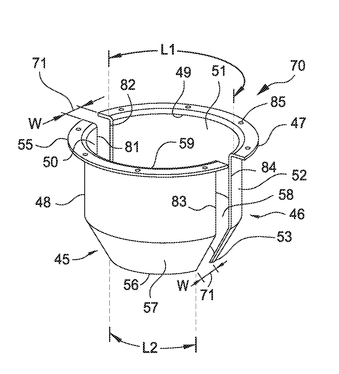
[0015]FIG. 2 illustrates a multi-slit upper cone 70 of the present disclosure, according to one implementation. The multi-slit upper cone 70 is shaped similar to the cone 30 of FIG. 1, however the multi-slit upper cone 70 has more than one slit 71, thus the multi-slit upper cone 70 includes at least a first body component 45 and a second body component 46. The body components 45 and 46 are positioned in FIG. 2 according to how the body components would be positioned within an epitaxy processing chamber 100 as shown in FIG. 3, according to one implementation. However, the present disclosure is not limited to this implementation, and the multi-slit upper cone 70 may have more than two slits 71, providing more than two body components, and the body components may be non-cylindrical.

[0016]Each body component 45, 46 of the multi-slit upper cone 70 of FIG. 2 has a partial cylindrical region having a concave inner surface 50, 51 and a convex outer surface 48, 52. Each surface 50, 51, 48, 5...


PUM

PropertyMeasurementUnit
widthaaaaaaaaaa
distanceaaaaaaaaaa
temperatureaaaaaaaaaa

Abstract

An epitaxial deposition chamber having an upper cone for controlling air flow above a dome in the chamber, such as a high growth rate epitaxy chamber, is described herein. The upper cone has first and second components separated by two or more gaps in the chamber, each component having a partial cylindrical region having a first concave inner surface, a first convex outer surface, and a fixed radius of curvature of the first concave inner surface, and a partial conical region extending from the partial cylindrical region, the partial conical region having a second concave inner surface, a second convex outer surface, and a varying radius of curvature of the second concave inner surface, wherein the second concave inner surface extends from the partial cylindrical region to a second radius of curvature less than the fixed radius of curvature.

Description

CROSS-REFERENCE TO RELATED APPLICATIONS[0001]This application claims benefit to Provisional Patent Application Ser. No. 62 / 380,114, filed on Aug. 26, 2016; Provisional Patent Application Ser. No. 62 / 393,942 filed on Sep. 13, 2016; and Provisional Patent Application Ser. No. 62 / 495,575 filed on Aug. 18, 2016, which are all incorporated by reference herein.BACKGROUNDField of the Invention[0002]The present disclosure generally relates to an apparatus for semiconductor processing. More specifically, the present disclosure relates to apparatus for controlling air flow in an epitaxy chamber.Description of the Related Art[0003]Epitaxy is a process commonly used in semiconductor processing to fabricate high quality materials with uniform electrical properties for semiconductor devices. In a typical epitaxy chamber, process gasses flow across a substrate in a direction parallel to the substrate to form a film on the substrate. The process gasses typically flow from one side of the chamber to...

Claims


Application Information

Patent Timeline
Patent Type & Authority Applications(United States)
IPC IPC(8): H01L21/67C23C16/48H01L21/20
CPCH01L21/67248C23C16/481C23C16/455C23C16/52C23C16/4405H01L21/20C23C16/45591C23C16/4401C23C16/4411C23C16/466C30B25/14H01L21/67017H01L21/67207
Inventor OKI, SHINICHIMORI, YOSHINOBUAOKI, YUJI
Owner APPLIED MATERIALS INC
Learn More