
Vehicle wheel alignment methods and systems

Active Publication Date: 2018-02-22
SNAP ON INC
View PDF0 Cites 8 Cited by
  • Summary
  • Abstract
  • Description
  • Claims
  • Application Information

AI Technical Summary

Benefits of technology

The patent describes a new wheel alignment system that solves problems with conventional systems. The system includes a pair of passive heads and an active reference pod. The passive heads are attached to the vehicle's wheels, and the active reference pod is attached to the vehicle's frame. The system uses image data from the passive heads and the active reference pod to calculate the alignment of the vehicle. The system is easier to use and more accurate than previous systems.

Problems solved by technology

The presence of such booms results in large, heavy, and expensive alignment heads, and the toe gauges can be obstructed easily by the vehicle body since they are in a fixed position on the alignment head (e.g., any rotation of the alignment head, for example resulting from the rolling forward or backward of the vehicle, may result in the toe gauge being obstructed).
The large beam can get in the way of shop operations, and the presence of the large beam results in a system that is large, heavy, and expensive.
Additionally, the large beam has minimum configurations options, and any deformation of the beam results in alignment measurement inaccuracies.
However, while the self-calibrating aligners address some of the drawbacks of the conventional and visual aligners noted above, the self-calibrating aligners rely on a calibration camera or a calibration target being attached to each alignment camera.
This set-up complexity restricts the acceptable locations of the alignment cameras (each having one of the calibration camera and the calibration target attached thereto), and limits some of the acceptable locations where the system can be used.
The presence of a rotation shaft, bearings, and other moving parts inside the wheel alignment heads increases cost and sensitivity to drops, and can add error into alignment measurements (e.g., as a result of stickiness in the bearings).
This makes the existing vision based aligners more expensive, harder to move (e.g., between racks in a vehicle repair shop), and requires an unobstructed visual path between the cameras on the external rig and the targets mounted on the vehicle wheels.
Thus, merely increasing the camera's FOV at the expense of lowered resolution is typically not desirable.
A first option, of bolting a hanger bracket on the rack, may require drilling into the rack which may compromise the structural integrity of the rack and may in some situations not be possible.
Furthermore, drilling into the rack makes for a time consuming installation process.

Method used


Image

  • Vehicle wheel alignment methods and systems
  • Vehicle wheel alignment methods and systems
  • Vehicle wheel alignment methods and systems

Examples


Embodiment Construction

[0034]In the following detailed description, numerous specific details are set forth by way of examples in order to provide a thorough understanding of the relevant teachings. However, it should be apparent to those skilled in the art that the present teachings may be practiced without such details. In other instances, well known methods, procedures, components, and / or circuitry have been described at a relatively high-level, without detail, in order to avoid unnecessarily obscuring aspects of the present teachings.

[0035]The various systems and methods disclosed herein relate to improved equipment and approaches to performing vehicle wheel alignment, including improved equipment and approaches for performing alignment measurements of wheels disposed on opposite sides of a vehicle.

[0036]In order to address the drawbacks detailed above, a side-to-side reference is provided that can be used when measuring the alignment of a vehicle, and that is not necessarily attached to the wheel ali...


PUM


Abstract

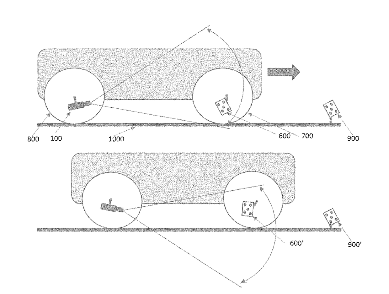
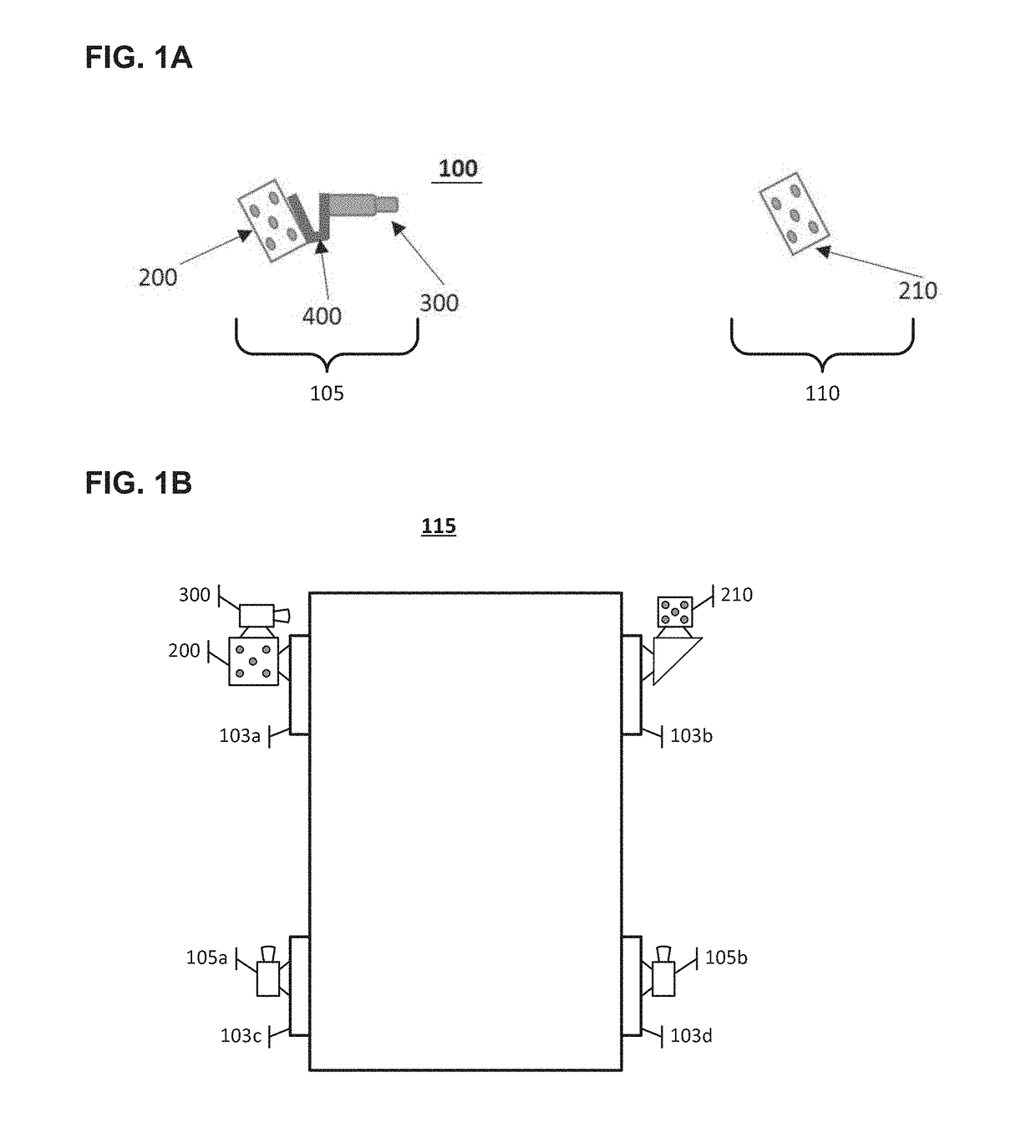
A wheel alignment system includes a side-to-side reference including an active reference pod and a passive reference pod disposed on opposite sides of the vehicle. The active reference pod includes a reference image sensor fixedly attached to a reference target, for mounting on a first side of the vehicle such that the reference image sensor produces image data including a perspective representation of the passive reference pod disposed on a second / opposite side of the vehicle. In operation, alignment cameras on the opposite sides of the vehicle capture perspective representations of targets mounted to vehicle wheels and of targets of the active and passive reference pods. A computer processes the image data to compute an alignment measurement of the vehicle based on a spatial relationship between the active reference pod and the passive reference pod determined according to the image data produced by the reference image sensor.

Description

CROSS-REFERENCE TO RELATED APPLICATIONS[0001]This application claims the benefit of U.S. Provisional Patent Applications No. 62 / 375,716, filed Aug. 16, 2016, and No. 62 / 377,954, filed Aug. 22, 2016, the disclosures of which are hereby incorporated by reference in their entireties.TECHNICAL FIELD[0002]The present subject matter relates to equipment and techniques for measuring alignment of wheels of a vehicle.BACKGROUND[0003]Wheel alignment equipment is used to measure the alignment of the wheels of a vehicle. Based on the measurements, adjustments to be made to the vehicle and wheels are determined in order to bring the wheels into alignment. As part of the alignment measurement process, the alignment equipment commonly measures the relative alignment of wheels disposed on each side of the vehicle separately (e.g., on a left side and a right side). In order to relate measurements taken on one side of the vehicle with measurements taken on the other / opposite side of the vehicle, the ...

Claims


Application Information

Patent Timeline
IPC IPC(8): G06T7/73G01B11/275G06T7/60H04N5/247
CPCG06T7/74G01B11/2755G06T2207/30252H04N5/247G06T7/60G01B2210/12G01B2210/143G01B2210/26G01B2210/30H04N23/90
Inventor KUNERT, JOEL A.CHEN, DARWIN Y.GILL, GEORGE M.GRAY, BRIAN K.ROGERS, STEVEN W.SWAYNE, RONALD D.JACKSON, DAVID A.HARRELL, RODNEYD'AGOSTINO, ROBERT J.MINOR, BRYAN C.SELLERS, ERIC R.LECRONE, SEAN P.KLOTZ, LARRY D.SPERRY, JONATHAN A.
Owner SNAP ON INC
Learn More