
LED bulb lamp

a technology of led light bulbs and filaments, applied in the field of lighting, can solve the problems of uneven brightness transit, personal safety risk, and the difficulty of filaments to generate the effect of even illumination light,

Active Publication Date: 2018-02-15
ZHEJIANG SUPER LIGHTING ELECTRIC APPLIANCE
View PDF3 Cites 24 Cited by
  • Summary
  • Abstract
  • Description
  • Claims
  • Application Information

AI Technical Summary

Benefits of technology

This patent describes LED bulb lamps with a reflecting film and an auxiliary piece to support the wires connecting electrodes to LED chips. This design prevents breakage of the wires and allows for flexibility in the shape of the LED filament, resulting in a more intricate and visually appealing lighting effect. Additionally, the LED bulb lamps are safer and can protect users from electric shock accidents.Another technical effect of this patent is the use of a substrate with wavelength conversion particles to achieve different lighting effects. These particles can be mixed into the LED chip, providing a more complete and varied color range.

Problems solved by technology

Nevertheless, the light shape curves of these LED bulb lamps are not smooth and have higher local jitter, which result in a situation in which the brightness transits unevenly.
In addition, the traditional LED bulb lamp generally has a glass lamp housing which is fragile and the glass fragments can hurt users easily, further, after being broken, the exposed and charged part in the lamp body, such as the light source, solder joints on the substrate or the wires on the lamp substrate etc., will lead to an accident of electric shock easily and result in the risk of personal safety.
A traditional light bulb having a tungsten filament can create the effect of even illumination light because of the nature of the tungsten filament; however, the LED filament is hard to generate the effect of even illumination light.
The LED filament of the LED light bulb is difficult to be bent to form curvature because the substrate plate causes less flexibility.
Further, electrodes on the LED filament and wires connecting the electrodes with the LEDs may be broken or disconnected when the LED filament is bent due to stress concentration.

Method used


Image

  • LED bulb lamp
  • LED bulb lamp
  • LED bulb lamp

Examples


Embodiment Construction

[0057]In order to make the objects, technical solutions and advantages of the invention more apparent, the invention will be further illustrated in details in connection with accompanying figures and embodiments hereinafter. It should be understood that the embodiments described herein are just for explanation, but not intended to limit the invention.

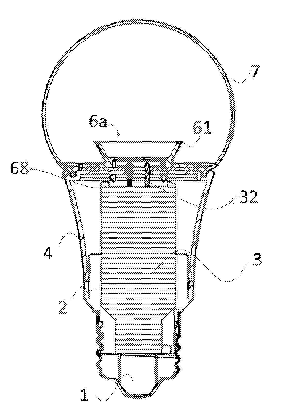
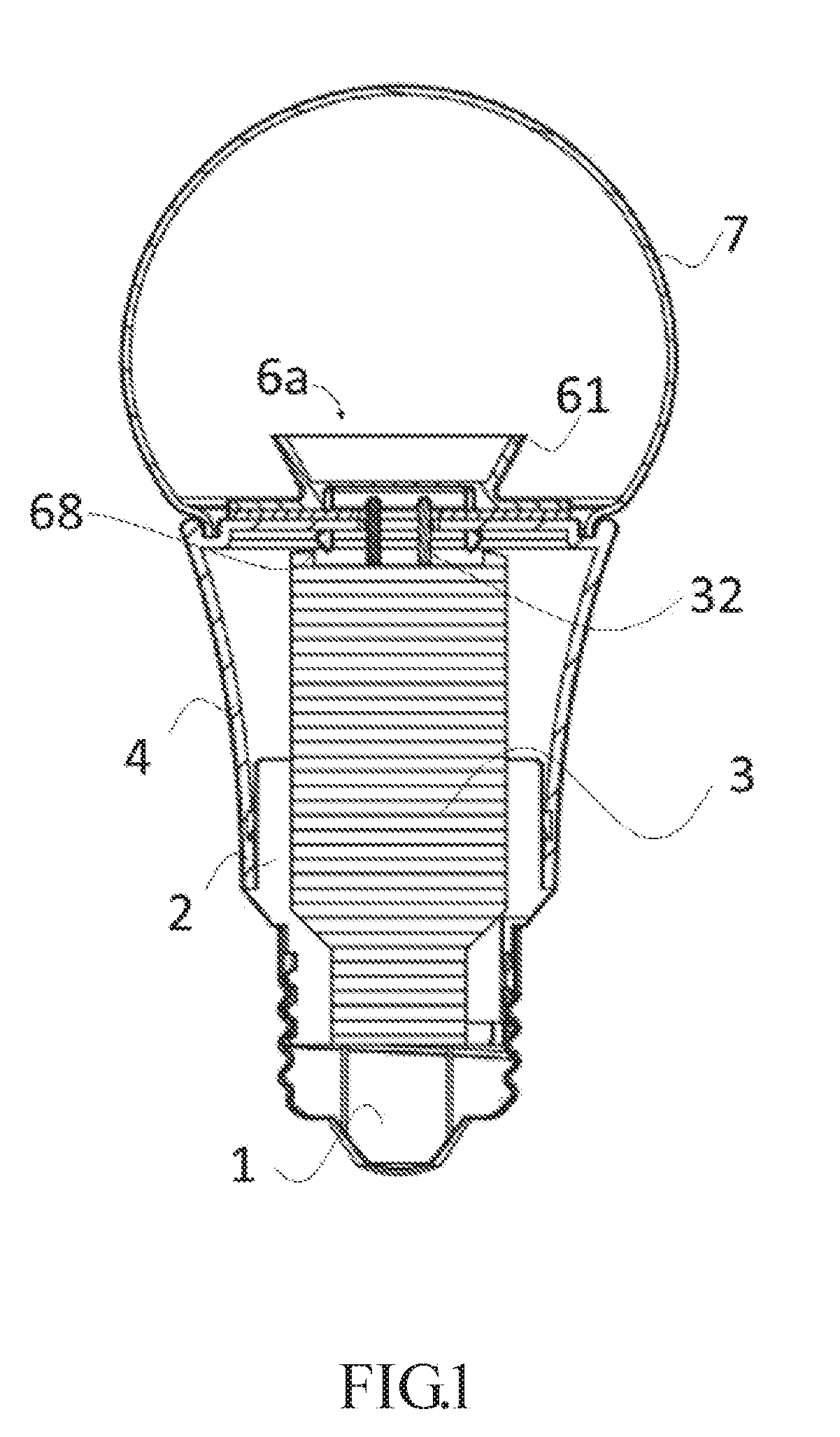
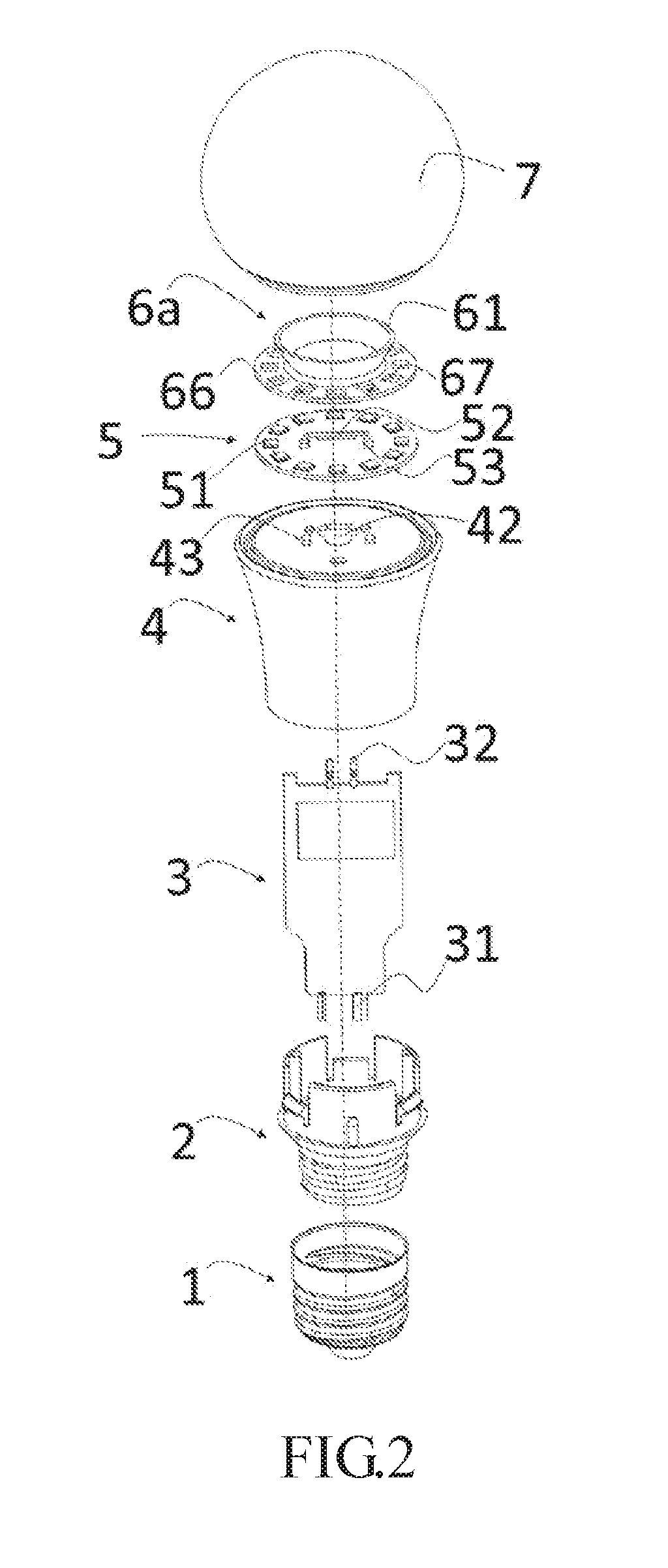
[0058]Referring to FIG. 1 to FIG. 6, an LED bulb lamp (also known as an LED light bulb) is provided according to an embodiment of this invention. FIG. 1 illustrates a longitudinal sectional view of the LED bulb lamp along the central axis according to an embodiment. FIG. 2 illustrates an exploded view of the LED bulb lamp according to an embodiment. FIG. 3 illustrates a structural schematic view of the electrical isolation assembly, the LED lamp substrate and the radiator after being assembled together according to an embodiment. FIG. 4 illustrates a longitudinal sectional view of the electrical isolation assembly along the central axis...


PUM


Abstract

An LED filament includes LED chips, two conductive electrodes, conductive wires, an enclosure coating, and one or more auxiliary piece. The LED chips are arranged in an array and electrically connected with one another. The two conductive electrodes are corresponding to the array. Each of the two conductive electrodes is electrically connected to a corresponding LED chip at an end of the array. The conductive wires electrically connect the LED chips and the two conductive electrodes. The conductive wires are respectively between every two adjacent LED chips of the array and between each of the two conductive electrodes and the corresponding LED chip at an end of the array. The enclosure coating is on two or more sides of the array and the two conductive electrodes. A portion of each of the two conductive electrodes is exposed from the enclosure. The auxiliary piece is disposed in the enclosure coating and overlaps one of the conductive wires between each of the two conductive electrodes and the corresponding one of the two LED chips respectively at two ends of the array on a radial direction of the LED filament.

Description

CROSS-REFERENCE TO RELATED APPLICATIONS[0001]This application is a continuation-in-part application claiming benefits of U.S. application Ser. No. 15 / 308,995 filed on 2016 Nov. 4, U.S. application Ser. No. 15 / 168,541 filed on 2016 May 31, and U.S. application Ser. No. 15 / 499,143 filed on 2017 Apr. 27, which is hereby incorporated by reference in their entirety.[0002]This application claims priority to Chinese Patent Applications No. 201410510593.6 filed on 2014 Sep. 28; No. 201510053077.X filed on 2015 Feb. 2; No. 201510489363.0 filed on 2015 Aug. 7; No. 201510555889.4 filed on 2015 Sep. 2; No. 201510316656.9 filed on 2015 Jun. 10; No. 201510347410.8 filed on 2015 Jun. 19; No. 201510502630.3 filed on 2015 Aug. 17; No. 201510966906.3 filed on 2015 Dec. 19; No. 201610041667.5 filed on 2016 Jan. 22; No. 201610281600.9 filed on 2016 Apr. 29; No. 201610272153.0 filed on 2016 Apr. 27; No. 201610394610.3 filed on 2016 Jun. 3; No. 201610586388.7 filed on 2016 Jul. 22; No. 201610544049.2 fil...

Claims


Application Information

Patent Timeline
Patent Type & Authority Applications(United States)
IPC IPC(8): F21K9/232F21V23/06F21K9/68
CPCF21K9/232F21K9/68F21V23/06F21V29/503F21Y2115/10F21K9/61F21Y2107/70F21Y2109/00H01L25/0753H01L33/62H01L2933/0091H01L33/505
Inventor JIANG, TAO
Owner ZHEJIANG SUPER LIGHTING ELECTRIC APPLIANCE
Learn More