Power converter

Active Publication Date: 2018-02-08
MITSUBISHI ELECTRIC CORP
View PDF22 Cites 4 Cited by
  • Summary
  • Abstract
  • Description
  • Claims
  • Application Information

AI Technical Summary

Benefits of technology

The present invention allows for the creation of an electric power converter that is low cost and efficient, and can handle a wide range of input-output voltages without strengthening the devices used for the conversion. The converter can also decrease the output voltage to 0V. This technology results in reduced costs and improved efficiency for power conversion.

Problems solved by technology

In addition, in order not to allow the short-circuit current flowing therethrough, it is suitable that an output voltage of a non-isolated converter is made higher so that the non-isolated converter is designed to always perform stepping up or boosting the voltage; however, a voltage applied across each of the devices increases, and so a device's withstand voltage should be heightened, causing a problem in occurrence of efficiency reduction and higher costs.

Method used


Image

  • Power converter
  • Power converter
  • Power converter

Examples


embodiment 1

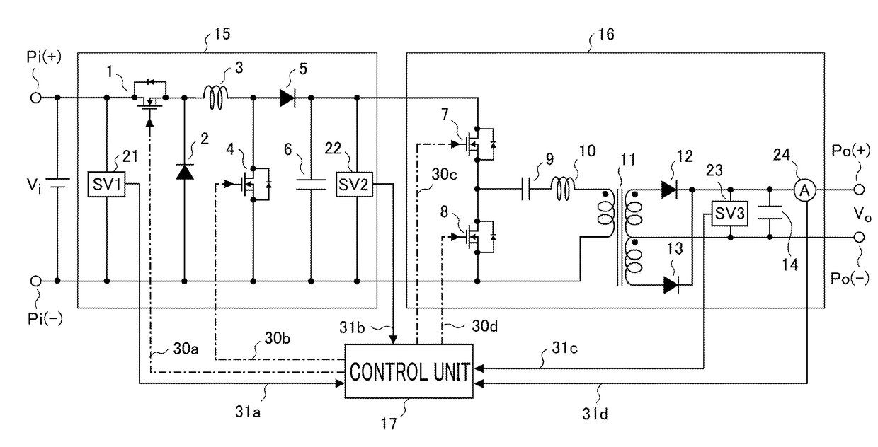
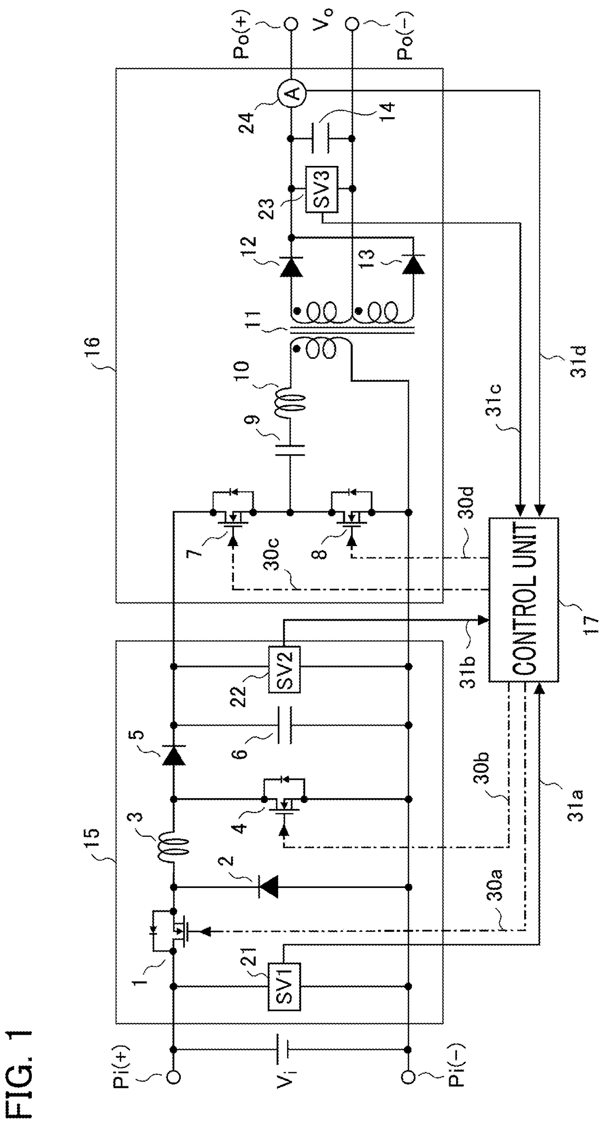
[0036]First, the explanation will be made referring to FIG. 1 through FIG. 9 for an electric power converter according to Embodiment 1 of the present invention. FIG. 1 is a schematic configuration diagram illustrating the electric power converter according to Embodiment 1; in FIG. 1, the electric power converter is a converter configured in a succession of two stages in which a non-isolated buck-boost converter circuit 15 is placed upstream of an isolated converter circuit 16 being an LLC (two inductors (LL) and a capacitor (C)) resonance converter. It is so arranged that an input voltage (DC voltage) Vi from input terminals Pi is stepped up or stepped down so as to be converted into an arbitrary DC voltage by means of the non-isolated buck-boost converter circuit 15; then, this DC voltage is inputted into the isolated converter circuit 16, and is thereby outputted at output terminals Po as an output voltage (DC voltage) Vo, which is supplied to a load not shown in the figure.

[0037]...

embodiment 2

[0098]Next, the explanation will be made referring to FIG. 10 through FIG. 15 for an electric power converter according to Embodiment 2 of the present invention. FIG. 10 is a schematic configuration diagram illustrating the electric power converter according to Embodiment 2; in FIG. 10, the electric power converter is a converter configured in a succession of two stages in which a polarity reversal type buck-boost converter circuit is provided as the non-isolated buck-boost converter circuit 15 upstream of the isolated converter circuit 16 that is a voltage resonance type converter.

[0099]It is so arranged that an input voltage Vi from input terminals Pi is stepped up or stepped down so as to be converted into an arbitrary DC voltage by means of the non-isolated buck-boost converter circuit 15 made of the polarity reversal type buck-boost converter circuit; then, this DC voltage is inputted into the isolated converter circuit 16, and is thereby outputted at output terminals Po as a D...

embodiment 3

[0152]Next, the explanation will be made referring to FIG. 16 for an electric power converter according to Embodiment 3 of the present invention. FIG. 16 is a schematic configuration diagram of the electric power converter according to Embodiment 3 of the present invention.

[0153]As illustrated in FIG. 16, the electric power converter is a converter configured in a succession of two stages in which the non-isolated buck-boost converter circuit 15 is placed upstream of the isolated converter circuit 16 being a half-bridge type converter. The non-isolated buck-boost converter circuit 15 is the same H-bridge type as that in Embodiment 1; however, the isolated converter circuit 16 is arranged to be of a half-bridge type in place of the full-bridge type of Embodiment 2.

[0154]An input voltage Vi from input terminals Pi is converted into an arbitrary DC voltage by means of the non-isolated buck-boost converter circuit 15, and an output voltage Vo is outputted by means of the isolated conver...


PUM


Abstract

An electric power converter is provided, at low costs and in high efficiency, which also enables voltage conversion to be capable of dealing with sharp load variation, even when input voltage and output current ranges are wide. The converter includes a non-isolated buck-boost converter circuit for outputting a DC voltage by increasing or decreasing a voltage being inputted into the circuit, an isolated converter circuit for outputting a DC voltage to a load by inputting a DC voltage outputted from the non-isolated buck-boost converter circuit, and a control unit for controlling the non-isolated buck-boost converter circuit and the isolated converter circuit, whereby the control unit adjusts using only the non-isolated buck-boost converter circuit, by performing the control of a buck-boost voltage ratio between the voltage inputted thereinto and an output voltage of the isolated converter circuit, so as to make the output voltage coincident with its target value.

Description

CROSS REFERENCE TO RELATED APPLICATIONS[0001]This application is a National Stage of International Application No. PCT / JP2015 / 056180 filed Mar. 3, 2015, the contents of all of which are incorporated herein by reference in their entirety.BACKGROUND OF THE INVENTIONField of the Invention[0002]The present invention relates to an electric power converter whose converter circuits each for converting an inputted DC voltage into a predetermined DC voltage are configured in a succession of two stages.Description of the Related ArtBACKGROUND ART[0003]In Japanese Laid-Open Patent Publication No. 2013-258860, a DC-DC converter is disclosed in its configuration including upstream thereof a non-isolated converter for stepping up or boosting a voltage from an input power source, and including downstream thereof an isolated bridge converter. The upstream non-isolated converter detects an output voltage, and controls so that an input voltage to the downstream isolated bridge converter becomes const...

Claims


Application Information

Patent Timeline
IPC IPC(8): H02M1/08H02M3/335
CPCH02M1/083H02M3/33523H02M2001/0058H02M3/155H02M3/28H02M3/3374Y02B70/10H02M1/0058
Inventor TANAKA, YUYA
Owner MITSUBISHI ELECTRIC CORP
Why Eureka
Try Eureka