
Conveyor and method for conveying a tire component

a technology applied in the field of conveying and tire components, can solve the problems of reducing the resistance or friction of sliding of the support surface with respect, affecting and fundamentally different elastic properties of rigid articles from elastic ones, so as to facilitate the sliding of the tire component and improve the centering of the tire component. , the effect of reducing friction

Active Publication Date: 2018-02-01
VMI HOLLAND BV
View PDF7 Cites 1 Cited by
  • Summary
  • Abstract
  • Description
  • Claims
  • Application Information

AI Technical Summary

Benefits of technology

The patent describes a new surface structure that can be used in the manufacturing of tires, specifically for retreading tires. These surface structures were previously thought to be too rigid for elastic tire components, but the patent shows that they can be used because the tire components are less susceptible to deformation. The surface structures can improve the centering and alignment of the tire component with respect to the drum or buffed carcass. The use of these surface structures can also reduce the complexity and maintenance requirements of the conveyor.

Problems solved by technology

Such rigid articles are fundamentally different from elastic, easily deformable and tacky tire components.
The known surface structures were therefore considered undesirable in the field of tire manufacturing at the time, mainly because of the prejudice that such surface structures would cause imprints on the deformable rubber material of tire components.
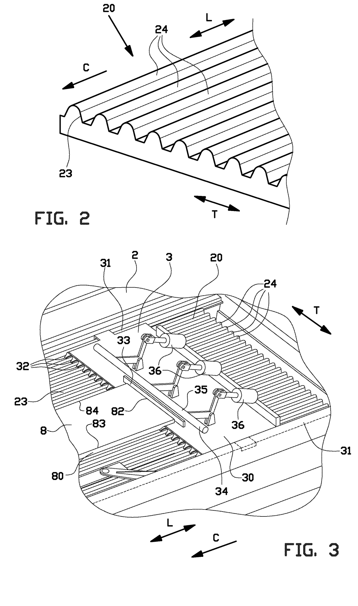
The corrugations can significantly reduce the contact area of the downwardly facing surface area of the tire component that is in contact with the support surface, thereby reducing the amount of resistance or friction to sliding of the support surface with respect to the tire component.

Method used


Image

  • Conveyor and method for conveying a tire component
  • Conveyor and method for conveying a tire component
  • Conveyor and method for conveying a tire component

Examples


Embodiment Construction

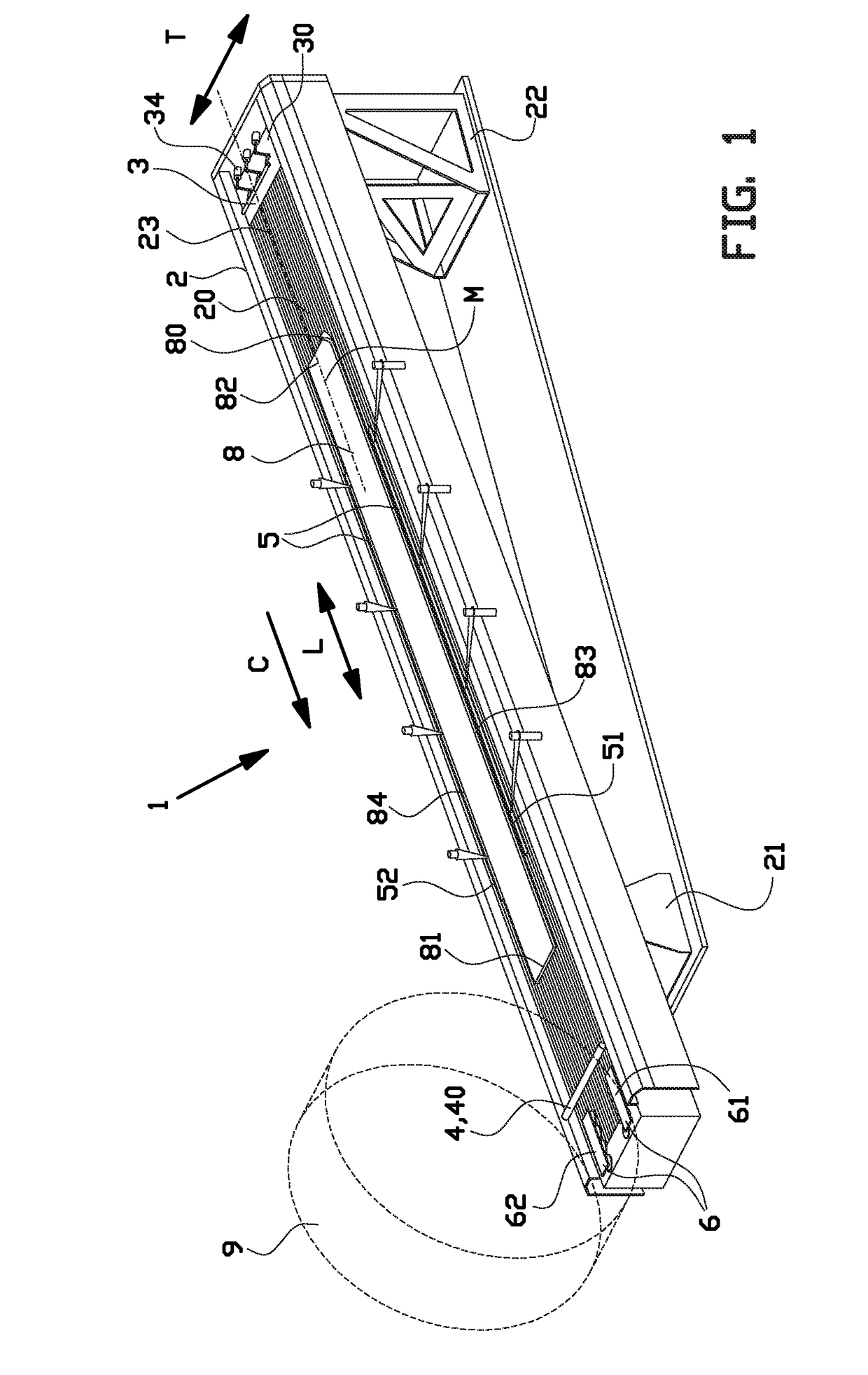
[0051]FIG. 1 shows a conveyor 1 according to the invention, for conveying a tire component 8 towards and / or into abutment with a drum 9.

[0052]In this exemplary embodiment, the tire component 8 is a freshly produced tread 8 for retreading purposes and the drum 9 is a retreading drum 9. Retreading is a remanufacturing process in which an old tread of a worn tire, supported on the retreading drum 9, is buffed away from a carcass (not shown) and replaced by the fresh tread 8 supplied by the conveyor 1. The conveyor 1 according to the invention may however also be used for conveying other tire components in other tire building processes.

[0053]As shown in FIG. 1, the conveyor 1 comprises a support track 2 that defines a support surface 20 for supporting the tire component 8. The support track 2 is provided with feet 21, 22 that are placed on a factory floor and that hold the support surface 20 at a certain height from the factory floor. In this case, the support surface 20 extends under a...


PUM

PropertyMeasurementUnit
distanceaaaaaaaaaa
distanceaaaaaaaaaa
frictionaaaaaaaaaa

Abstract

Provided is a conveyor for conveying a tire component, in particular a tread for retreading, wherein the conveyor includes a support surface that extends in a direction of conveyance to support the tire component during conveyance in the direction of conveyance, wherein the support surface is provided with a surface structure that is arranged to contact seventy-five percent or less than seventy-five percent of the downwardly facing surface area of the tire component, wherein the support surface is arranged to be held stationary during conveyance of the tire component and wherein the conveyor is provided with one or more manipulators to manipulate the position of the tire component on the stationary support surface by sliding the tire component over the stationary support surface.

Description

BACKGROUND[0001]The invention relates to a conveyor and method for conveying a tire component, in particular a tread for retreading.[0002]Known conveyors for retreading comprise rollers which are actively driven to convey a fresh tire tread to a buffed carcass at the downstream end of the conveyor. These known roller conveyors are complex, expensive and require frequent maintenance to prevent down time. Furthermore, complex gripping means, such as vacuum cups, magnets and / or jaws are used to pick up and clamp the tire component during handling.[0003]DE 1 904 481 A discloses a device for feeding a tread strip to a pressing machine. The device comprises a supply table and a transporting means for transporting the tread over the supply table towards the pressing machine. DE 1 904 481A teaches that the surface of the supply table has to be ‘even and smooth’ to generate as little friction as possible between the tread and the supply table during sliding of said tread over the supply tabl...

Claims


Application Information

Patent Timeline
Patent Type & Authority Applications(United States)
IPC IPC(8): B29C31/08B29D30/30B29D30/58
CPCB29C31/085B29D30/58B29D30/3007B29C31/08B29D30/30B29D30/54B65G47/82B65G2201/0273
Inventor KELLIJ, EGBERT GRIETINUSVAN ASSENBERGH, KAREL JOHANNESRUPERT, THIJS HUBERTHESSELINK, RUUD ALBERTUS GERHARDUS
Owner VMI HOLLAND BV
Learn More