Clamping device for stretching a threaded bolt

a technology of threaded bolts and clamping devices, which is applied in the direction of measuring devices, metal working apparatuses, instruments, etc., can solve the problems of large design work, high mechanical load on sensors, and large design work, and achieves the effect of increasing operational reliability, simplifying design, and simplifying design

Active Publication Date: 2018-01-18
HOHMANN JORG +1
View PDF3 Cites 1 Cited by
  • Summary
  • Abstract
  • Description
  • Claims
  • Application Information

AI Technical Summary

Benefits of technology

[0018]In yet another advantageous embodiment of the invention, the hydraulic control unit is designed in such a way that the hydraulic device is not released to build up pressure until a certain minimum thread engagement length has been reached. Therefore, once a value for the minimum thread engagement length—which has been predefined by the user or has been automatically predefined—has been reached, it becomes possible to pump hydraulic fluid into the piston-cylinder unit and place the changeover bush under tensile force. Such a device is used for safety, in particular, and reduces the risk of the changeover bush breaking loose or sliding off the threaded bolt if the thread engagement is insufficient. In addition, such a design simplifies the operation of the clamping device in such a way that it allows for a fully automatic operation of the clamping device without active engagement by a person. The hydraulic device is controlled according to the thread engagement that is actually present. Increased operational reliability is achieved as a result. One reason therefor is that errors in measurement resulting from human involvement are nearly entirely ruled out.
[0019]In yet another advantageous embodiment of the invention, the sensor element is disposed on a sensor housing which, in turn, is provided with a threaded projection. This threaded projection is screwed into a corresponding thread receptacle of the changeover bush. The sensor element or the sensor element fastened on the sensor housing can therefore be securely connected to the changeover bush in a simple way. This embodiment also simplifies the design according to the invention and simultaneously increases the operational reliability.
[0020]It is also advantageous when the hydraulic control unit is provided with visual display means. These means display, for example, the measured thread engagement and the minimum thread engagement length. Alternatively or additionally, it is possible to display or acoustically signal whether the thread engagement that has been achieved is sufficient.

Problems solved by technology

Such a design requires a relatively large amount of design work since it requires an exact match between the bolt, the measuring arrangement, and the changeover bush.
This results in a considerable amount of design work.
In the case of the clamping devices known from the prior art, which comprise sensor arrangements having direct contact with the bolt to be clamped, the sensor may be subjected to high mechanical loads.
One aspect shared by all these devices is that the tensile stress can be calculated from the measurement data, but the thread engagement cannot be directly calculated in this way.

Method used


Image

  • Clamping device for stretching a threaded bolt
  • Clamping device for stretching a threaded bolt
  • Clamping device for stretching a threaded bolt

Examples


Embodiment Construction

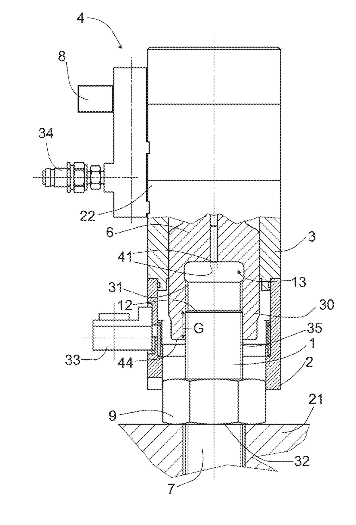
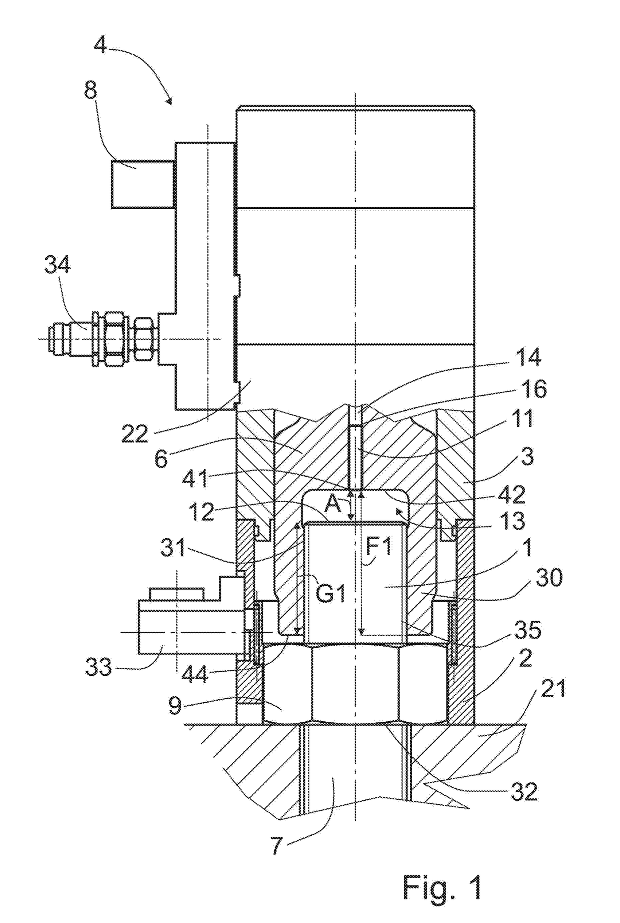
[0027]The clamping device according to the invention is used for tightening, re-tightening, or even loosening threaded connections, in particular threaded connections in which a threaded bolt 7 has been clamped via a nut 9 against another machine part 21.

[0028]During operation, the clamping device can exert a preload force onto the threaded bolt 7. This is referred to synonymously as pulling on the threaded bolt 7 or stretching the threaded bolt 7. During this preloading, the nut 9 screwed onto the threaded bolt 7 can be tightened, re-tightened, or loosened, if necessary.

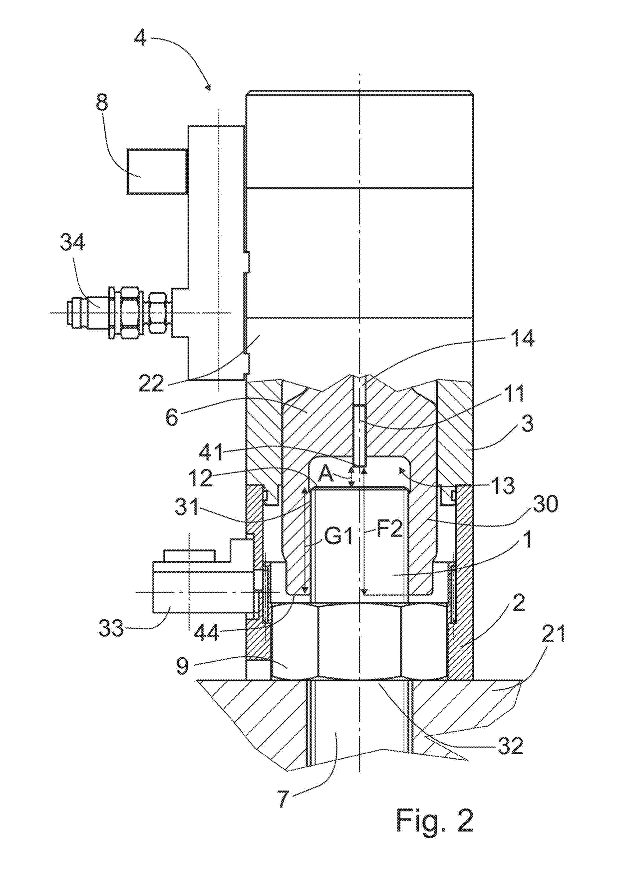
[0029]A clamping device according to the invention is shown in the installation position in two different embodiments in FIGS. 1 and 2. The two embodiments are identical with respect to their essential components.

[0030]A central component of the clamping device is a changeover bush 6 which is surrounded in part by a support tube 2 and in part by a cylinder 3. At its one end, the changeover bush 6 is designed to be a...


PUM


Abstract

A clamping device for stretching a threaded bolt by pulling on its threaded end section has a support tube surrounding the threaded end section, a cylinder disposed in extension of the support tube, a piston axially movable therein, a changeover bush to be screwed onto the threaded end section and carried along axially by the piston, a hydraulic device for the piston, and a signal link between hydraulic device and a device for detecting the extent of the thread engagement between the changeover bush and the threaded end section. A contactless measurement of the thread engagement between changeover bush and bolt to be clamped for measuring the thread engagement is provided in that the device for detecting the extent of the thread engagement includes a sensor element fastened on the changeover bush, which is positioned axially opposite the end face of the threaded bolt with axial separation.

Description

BACKGROUND OF THE INVENTION[0001]The invention relates to a clamping device for stretching a threaded bolt by pulling on its threaded end section, said clamping device comprising a support tube surrounding the threaded end section, a cylinder which is disposed in extension of the support tube and comprises at least one piston which is axially movable therein by means of hydraulic forces, a changeover bush which can be screwed together with the threaded end section and is designed to be carried along axially by the piston, a hydraulic device for the hydraulic supply of the piston, and a signal link between the hydraulic device and a device for detecting the extent of the thread engagement between the changeover bush and the threaded end section.[0002]Clamping devices for stretching threaded bolts are known from the prior art. The clamping device disclosed in U.S. Pat. No. 5,452,629 comprises a measuring arrangement for determining the tensile stress. The measuring arrangement essenti...

Claims


Application Information

Patent Timeline
Patent Type & Authority Applications(United States)
IPC IPC(8): B23P19/06B25B29/02G01B21/02G01B21/16
CPCB23P19/067G01B21/02G01B21/16B25B29/02
Inventor HOHMANN, JORGHOHMANN, FRANK
Owner HOHMANN JORG
Why Eureka
Try Eureka