
Robot for minimally invasive neurosurgery

a robotic and neurosurgery technology, applied in the field of robotic systems, can solve the problems of debilitating patient side effects, complex brain surgery, traumatic open skull surgery, etc., and achieve the effects of reducing brain shift, accurate positioning and movement, and maintaining the spatial accuracy of preoperative images

Active Publication Date: 2018-01-18
TECHNION RES & DEV FOUND LTD
View PDF0 Cites 4 Cited by
  • Summary
  • Abstract
  • Description
  • Claims
  • Application Information

AI Technical Summary

Benefits of technology

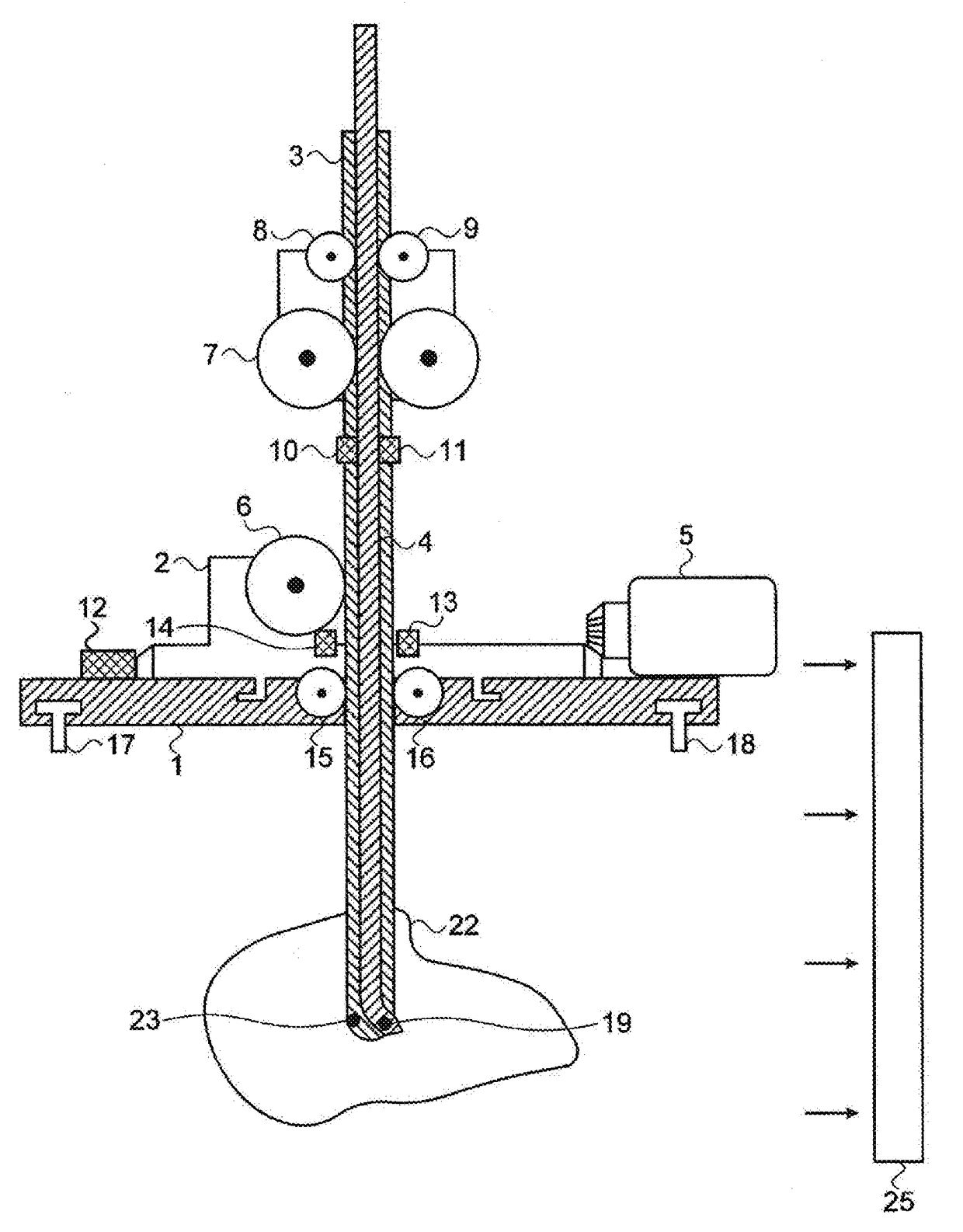
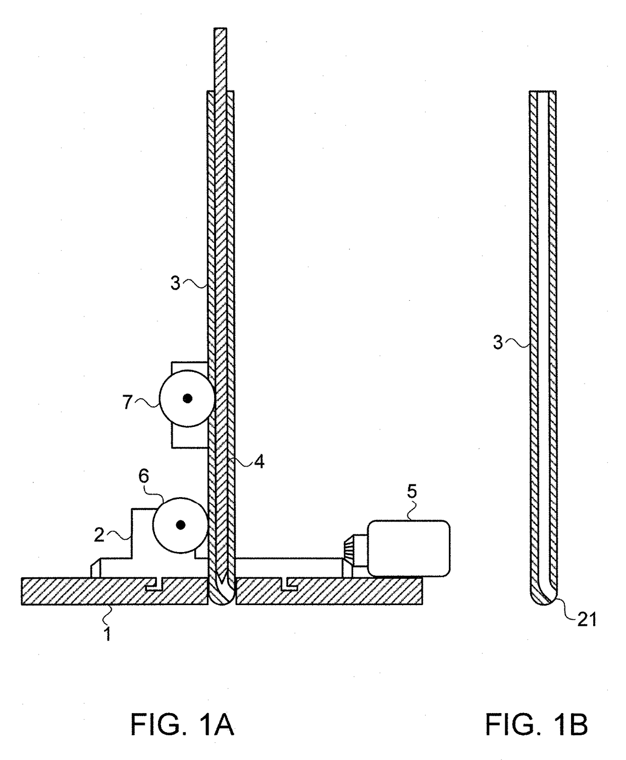
The patent describes new automated robot-based platforms for minimally-invasive neurosurgical procedures such as brain tumor resection or biopsy extraction. Unlike other robotic approaches that mimic the surgeon's hand motion, this technology uses the unique capabilities of robotic systems for minimally-invasive access to regions of the brain with minimal collateral tissue damage. By mapping the region to be treated using imaging modalities, the surgeon decides on the best path to reach the tumor, with minimal trauma to surrounding brain tissue. The small access path improves operation accuracy and reduces tissue damage and morbidity. The robotic device consists of a baseplate, a rotatable element, a cannula, and a flexible needle with a structure that enables it to exit the non-axial aperture and continue the motion out of the aperture to the target region without losing its mechanical properties. This technology allows for safer and more precise brain surgery.

Problems solved by technology

As of today, brain surgeries remain complex and risky.
Conventional open skull surgery is traumatic, may have debilitating side effects to the patient and generally requires long recovery time.
The time taken to perform the surgery may be tedious and decreases the efficiency of the medical staff.
The complexity of the operations often prevents repeatability if required.
The operation itself may cause a brain-shift, and for operations such as tumor resection, the original position of the tumor may be dislocated so that pre-operative planning may no longer be accurate intraoperatively.

Method used


Image

  • Robot for minimally invasive neurosurgery
  • Robot for minimally invasive neurosurgery
  • Robot for minimally invasive neurosurgery

Examples


Embodiment Construction

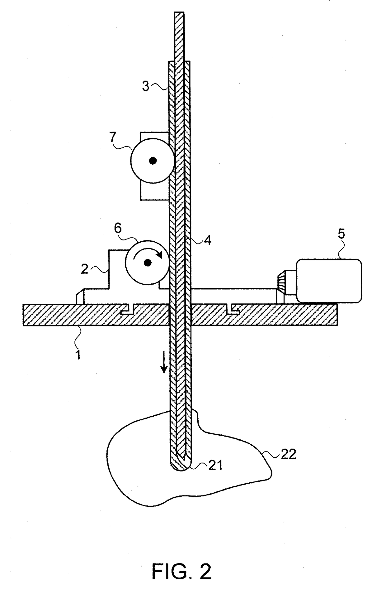
[0046]Reference is now made to FIGS. 1A and 1B, which illustrate schematically an exemplary implementation of a robotically controlled neurosurgical apparatus according to the novel designs presented in this disclosure. A central feature of this neurosurgical robot implementation is a combination of a flexible needle 4 which can be controllably inserted into an external rigid cannular needle 3. Although the flexible needle is shown in the drawings of this disclosure as a solid needle, it can, as previously mentioned, be either solid or cannulated. The shape of the external rigid needle is shown in FIG. 1B. At its distal tip 21, the bore of the external needle is diverted laterally, so that the distal opening is directed sideways from the bore of the needle, at an angle to the axis of the bore of the needle. In FIGS. 1A and 1B, the exit angle is shown as approximately 45° to the cannula axis, though it is to be understood that this angle can be selected to enable ease of passage of t...


PUM


Abstract

A robotic device for performing intracranial procedures, comprising a baseplate for mounting on the subject's skull and a rotatable base element rotating on the baseplate. The rotatable base element has a central opening through which a cannulated needle can protrude such that it can rotate around an axis perpendicular to the baseplate. This cannulated needle is robotically controlled to provide motion into and out of the subject's skull. A flexible needle is disposed coaxially within the cannulated needle, and it is controlled to move into and out of a non-axial aperture in the distal part of the cannulated needle. Coordinated control of the insertion motion of the cannulated and flexible needles, and rotation of the combined cannulated / flexible needle assembly enables access to be obtained to a volume of a region of the brain having lateral dimensions substantially larger than the width of the cannulated needle.

Description

CROSS-REFERENCE TO RELATED APPLICATIONS[0001]This application is a continuation of U.S. patent application Ser. No. 13 / 941,607, filed Jul. 15, 2013, which is a continuation-in part of PCT International Application No. PCT / IL2012 / 000022, which has an international filing date of Jan. 15, 2012, and which claims the benefit of priority from U.S. Provisional Patent Application No. 61 / 457,147, filed on Jan. 14, 2011, the disclosures of which are incorporated herein by reference in their entirety.FIELD OF THE INVENTION[0002]The present invention relates to the field of robotic systems for use in minimally invasive surgical and diagnostic procedures, especially for use in performing cranial neurosurgery.BACKGROUND OF THE INVENTION[0003]As of today, brain surgeries remain complex and risky. Conventional open skull surgery is traumatic, may have debilitating side effects to the patient and generally requires long recovery time. The time taken to perform the surgery may be tedious and decreas...

Claims


Application Information

Patent Timeline
Patent Type & Authority Applications(United States)
IPC IPC(8): A61B34/10A61B34/30A61B90/11A61B10/02A61B34/20A61B90/00
CPCA61B34/10A61B90/39A61B2034/2059A61B34/30A61B10/0233A61B90/11A61B18/1477A61B18/082A61B2018/2005A61N2007/0047A61N2007/003A61B2018/00446A61B2034/301
Inventor ZARROUK, DAVIDSHOHAM, MOSHEZAAROOR, MENASHEZISO, HADAS
Owner TECHNION RES & DEV FOUND LTD
Learn More