Rain-tight connector

Inactive Publication Date: 2018-01-11
YANG JINXING
View PDF2 Cites 2 Cited by
  • Summary
  • Abstract
  • Description
  • Claims
  • Application Information

AI Technical Summary

Benefits of technology

The patent describes a compression ring used in a fitting for a gas pipe. The compression ring has a central part with a hollow ridge that acts as a stop, preventing the tightening of the gas pipe nut beyond a certain point. The ends of the compression ring are flat and designed to create a tight seal and secure the metal tube in place. A locking unit with teeth can also be inserted to further strengthen the structure and secure the metal tube. The technical effect of this invention is to create a reliable and secure fitting for gas pipes.

Problems solved by technology

However, the locking device in Auray does not seem to securely hold the metal tube.

Method used


Image

  • Rain-tight connector
  • Rain-tight connector
  • Rain-tight connector

Examples


Embodiment Construction

[0018]The detailed description set forth below is intended as a description of the presently exemplary device provided in accordance with aspects of the present invention and is not intended to represent the only forms in which the present invention may be prepared or utilized. It is to be understood, rather, that the same or equivalent functions and components may be accomplished by different embodiments that are also intended to be encompassed within the spirit and scope of the invention.

[0019]Unless defined otherwise, all technical and scientific terms used herein have the same meaning as commonly understood to one of ordinary skill in the art to which this invention belongs. Although any methods, devices and materials similar or equivalent to those described can be used in the practice or testing of the invention, the exemplary methods, devices and materials are now described.

[0020]All publications mentioned are incorporated by reference for the purpose of describing and disclos...


PUM


Abstract

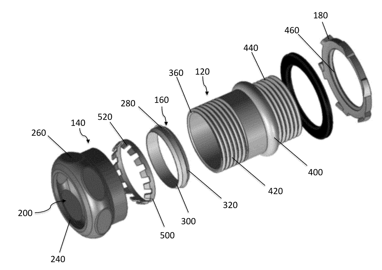
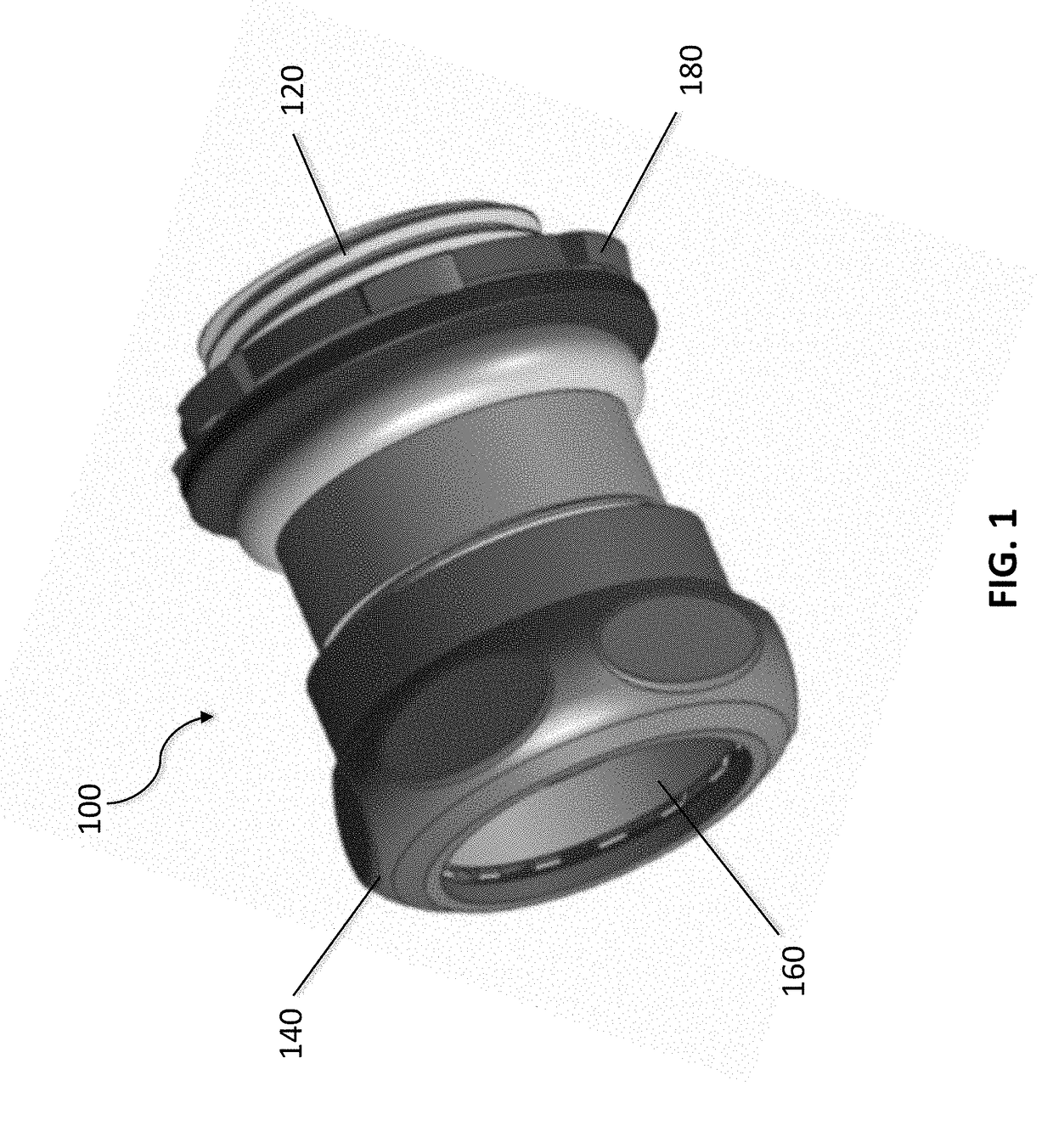
A rain tight connector may include a connector body, a gland nut coupled to the connector body, and a compression ring. A locknut is coupled to the connector body on the end portion thereof opposite to the gland nut. The compression ring includes a central portion and first and second coaxial end portions. The central portion defines an annular stop. A locking unit with a plurality of locking teeth is provided in the present invention to further secure the metal tube. More specifically, the locking unit can be inserted into the compressing ring to strengthen its structure to securely hole the metal tube

Description

CROSS-REFERENCE TO RELATED APPLICATIONS[0001]This application claims priority under 35 U.S.C. §119 (e) to U.S. Provisional Patent Application Ser. No. 62 / 358,487, filed on Jul. 5, 2016, the entire contents of which are hereby incorporated by reference.FIELD OF THE INVENTION[0002]The present invention relates to rain-tight conduit fittings, and more particularly, to rain-tight conduit fittings used to terminate flexible conduit to electrical enclosures.BACKGROUND OF THE INVENTION[0003]In the field of wiring homes and buildings, whether for new construction or for improvements or expansion, substantial development and product improvements have been made. Typically, these improvements are directed to enabling installers to securely mount any desired wiring in any desired location in the most efficient and quickest manner.[0004]In any particular installation or location, various cables must be interconnected to each other as well as connected to the primary power supply in a suitable po...

Claims


Application Information

Patent Timeline
IPC IPC(8): H02G3/06F16L19/08F16L19/065
CPCH02G3/0691F16L19/08F16L19/065F16L37/091
Inventor YANG, JINXING
Owner YANG JINXING
Why Eureka
Try Eureka