Image processing device and image processing method
- Summary
- Abstract
- Description
- Claims
- Application Information
AI Technical Summary
Benefits of technology
Problems solved by technology
Method used
Image
Examples
first embodiment
(Typical Configuration of the Image Display System as the First Embodiment)
[0094]FIG. 9 is a block diagram depicting a typical configuration of an image display system as the first embodiment of the present disclosure.
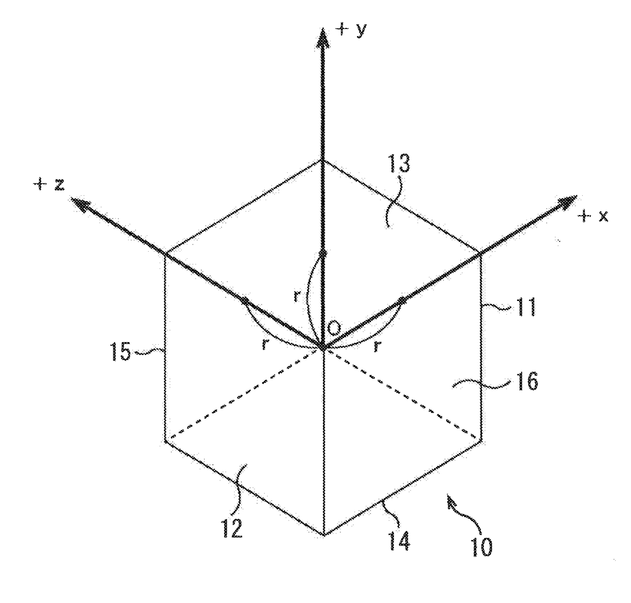
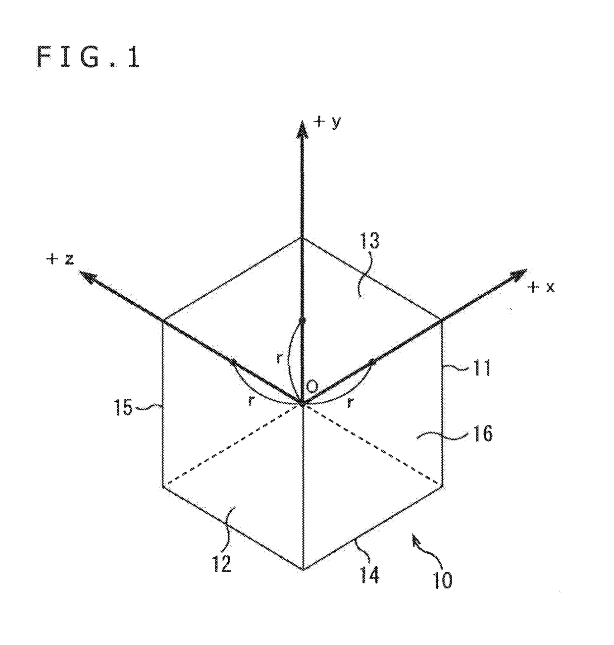
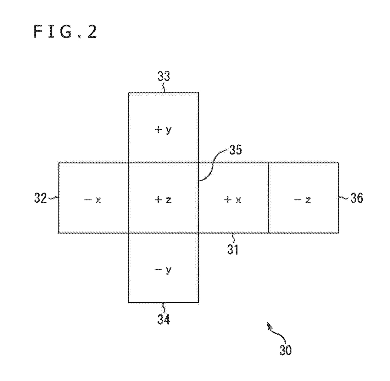
[0095]An image display system 130 in FIG. 9 is made up of a multi-camera apparatus 231, a content server 132, a home server 133, a converter 134, and a head-mounted display 135. The image display system 130 generates the celestial sphere image 30 from images captured by the multi-camera apparatus 131 and displays the image of the user's field of view derived from the generated celestial sphere image 30.
[0096]Specifically, the multi-camera apparatus 131 in the image display system 130 is constituted by multiple cameras. The cameras capture images individually to form omnidirectional images in units of frames. The multi-camera apparatus 131 supplies the captured omnidirectional images to the content server 132.
[0097]From the captured images supplied by the multi-camera a...
second embodiment
[0246](Explanation of the Method for Generating the Celestial Sphere Image with the Second Embodiment)
[0247]FIG. 20 is a schematic view depicting a sphere as a 3D model to which images are mapped by a method for generating a celestial sphere image in the second embodiment (the method is called new equidistant cylindrical projection hereunder).
[0248]As depicted in FIG. 20, images are mapped to the surface of a sphere 280 by new equidistant cylindrical projection as by equidistant cylindrical projection, except that the surface of the sphere 280 is divided vertically into three planes, of which the middle plane is further divided horizontally into four, to eventually make up six planes 281 to 286 of approximately the same area. In the example of FIG. 20, the middle plane of the sphere 280 is divided into the planes 283 to 286 in such a manner that a front 291 of the image mapped to the sphere 280 is positioned at the center on the boundary between the planes 284 and 285 and that a bac...
third embodiment
(Typical Configuration of the Image Display System as the Third Embodiment)
[0298]FIG. 29 is a block diagram depicting a typical configuration of an image display system as the third embodiment of the present disclosure.
[0299]Of the components depicted in FIG. 29, those that are the same as in FIG. 9 are assigned the same reference numerals. Redundant explanations of the components are omitted hereunder where appropriate.
[0300]An image display system 470 in FIG. 29 is configured differently from the image display system 130 in FIG. 9 in that a home server 471 and a display unit 472 replace the home server 133 and the head-mounted display 135, respectively, that the converter 134 is omitted, and that a controller 473 is provided.
[0301]In the image display system 370, the user operates the controller 473 to input the user's position and visual line vector. The display unit 472 displays a display image reflecting the input position and visual line vector.
[0302]Specifically, the home ser...
PUM
 Abstract
Description
Claims
Application Information
 - R&D
- Intellectual Property
- Life Sciences
- Materials
- Tech Scout
- Unparalleled Data Quality
- Higher Quality Content
- 60% Fewer Hallucinations
Browse by: Latest US Patents, China's latest patents, Technical Efficacy Thesaurus, Application Domain, Technology Topic, Popular Technical Reports.
© 2025 PatSnap. All rights reserved.Legal|Privacy policy|Modern Slavery Act Transparency Statement|Sitemap|About US| Contact US: help@patsnap.com


