Eureka AIR delivers breakthrough ideas for toughest innovation challenges, trusted by R&D personnel around the world.

Electrical serially-connected control system

a control system and serial connection technology, applied in the field of control systems, can solve the problems of ineffective management of motors, inability to control and drive motors, and inability to operate effectively, so as to simplify the operation of controlling and driving motors and increase the convenience of drive and control operation

Inactive Publication Date: 2018-01-04
NAT CHIN YI UNIV TECH
View PDF0 Cites 4 Cited by
  • Summary
  • Abstract
  • Description
  • Claims
  • Application Information

AI Technical Summary

Benefits of technology

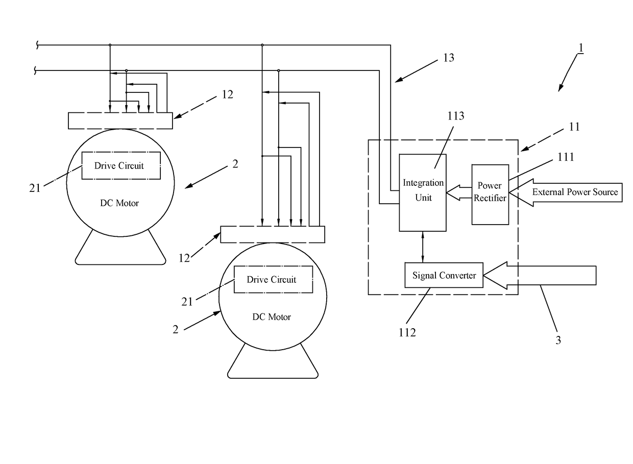
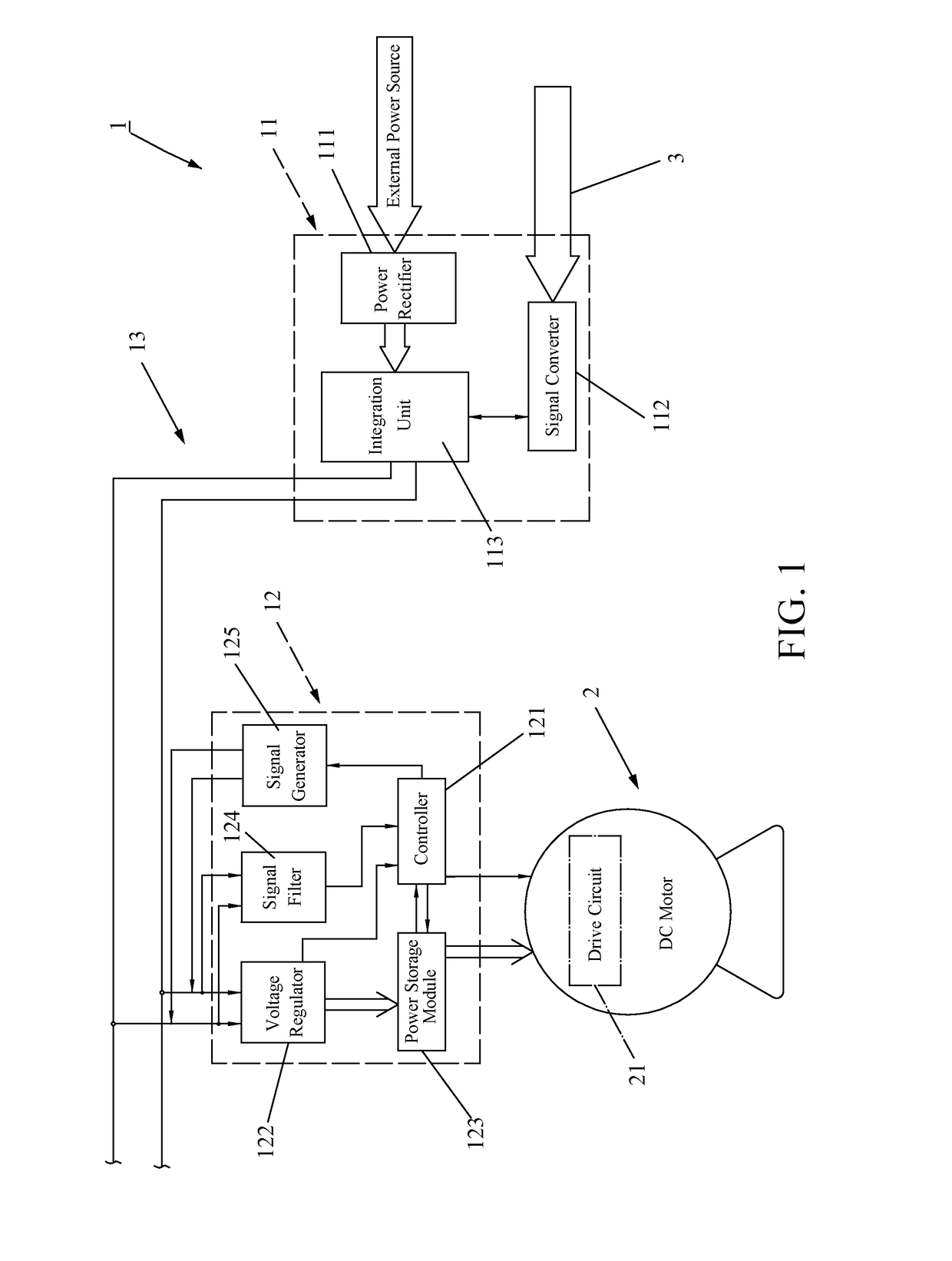
This patent describes a control system for multiple motors that are connected in series. The system includes a control device with a power rectifier, signal converter, and integration unit to generate command signals. Each motor has a separate processing device with a voltage regulator, power storage module, signal filter, controller, and signal generator. The controller activates the motor based on the restored command signal, while the signal generator collects and transmits reporting signals to the control device for mutual communication. The system simplifies motor control, increases operational convenience, and is adaptable for several motors.

Problems solved by technology

However, the additional control lines complicate the whole circuit.
Meanwhile, during the operation of activating each motor, each motor may operate unsuccessfully or even get damaged if the control lines are arranged improperly or mistaken in placement.
Hence, the motors are managed ineffectively.
Besides, the cost of setup is increased greatly.
Further, the more the user add the motors, the greater the interference during the transmission of the command signals is.
Thus, the control difficulty of the motors is increased.

Method used


Image

  • Electrical serially-connected control system
  • Electrical serially-connected control system
  • Electrical serially-connected control system

Examples


Embodiment Construction

[0015]Referring to FIG. 1, a first preferred embodiment of an electrical serially-connected control system 1 of this invention is applied to control and drive a plurality of DC motors 2 which are organized in series in this preferred embodiment. The electrical serially-connected control system 1 includes a control device 11 connected to an external power source and an external communication interface 3, at least one processing device 12 applied to control an operation of the DC motors 2, and a transmission medium 13 connected to the control device 11 and the processing device 12 respectively.

[0016]The control device 11 has a power rectifier 111 connected to the external power source, a signal converter 112 connected the external communication interface 3, and an integration unit 113 connected to the power rectifier 111 and the signal converter 112 respectively. The power rectifier 111 transforms power received from the external power source, in other words, the power rectifier 111 t...


PUM


Abstract

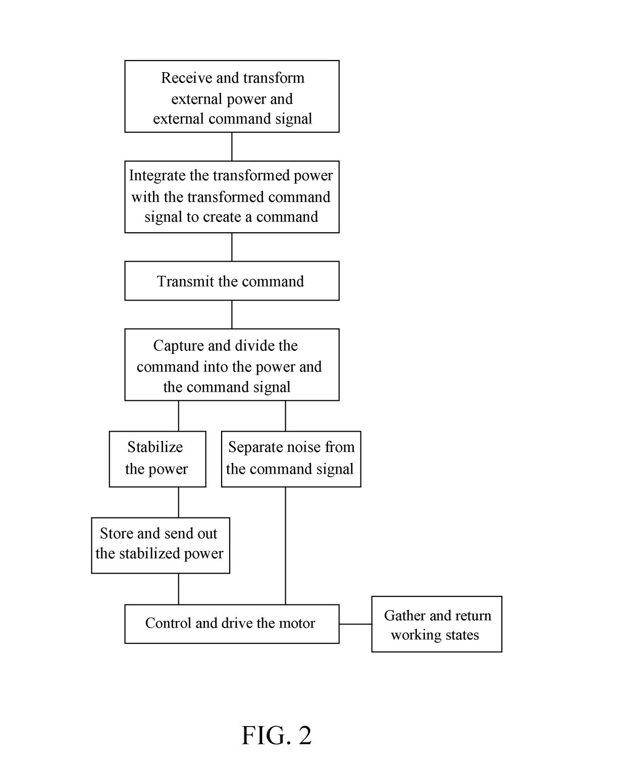
An electrical serially-connected control system for driving motors in series includes a control device, at least one processing device, and a transmission medium connected between the two devices for mutual communication. The control device includes a power rectifier transforming an external power, a signal converter converting each external command signal, and an integration unit connected to the rectifier and the converter for integrating the transformed power with each converted command signal to create commands. The processing device includes a voltage regulator connected to the transmission medium for stabilizing the power come from the command, a power storage module connected to the voltage regulator and each motor, a signal filter connected to the transmission medium for processing the command signal come from the command, a controller connected with the voltage regulator, the power storage module and the signal filter, and a signal generator connected to the controller.

Description

BACKGROUND OF THE INVENTION1. Field of the Invention[0001]This invention relates to a control system and relates particularly to an electrical serially-connected control system.2. Description of the Related Art[0002]A motor is one of the essential parts in not only industrial field but also scientific field. Of all the motors used by man can be divided into DC motors and AC motors. Generally, an operation of a single motor is executed through a controller and a control line. The corresponding control lines should be added to each motor for transmitting power and command signals if the user attempts to operate several motors simultaneously. However, the additional control lines complicate the whole circuit. Meanwhile, during the operation of activating each motor, each motor may operate unsuccessfully or even get damaged if the control lines are arranged improperly or mistaken in placement. Hence, the motors are managed ineffectively. Besides, the cost of setup is increased greatly. ...

Claims


Application Information

Patent Timeline
IPC IPC(8): H02P5/60
CPCH02P5/60H02P5/00H02P5/68H02P5/74
Inventor PU, WEN-CHENG
Owner NAT CHIN YI UNIV TECH
Why Eureka
Eureka Blog
Learn More