Orbit control device and satellite
a control device and orbital technology, applied in the field of orbit control devices, can solve the problems of gradual change of latitude and longitude, and achieve the effect of low calculation cos
- Summary
- Abstract
- Description
- Claims
- Application Information
AI Technical Summary
Benefits of technology
Problems solved by technology
Method used
Image
Examples
embodiment 1
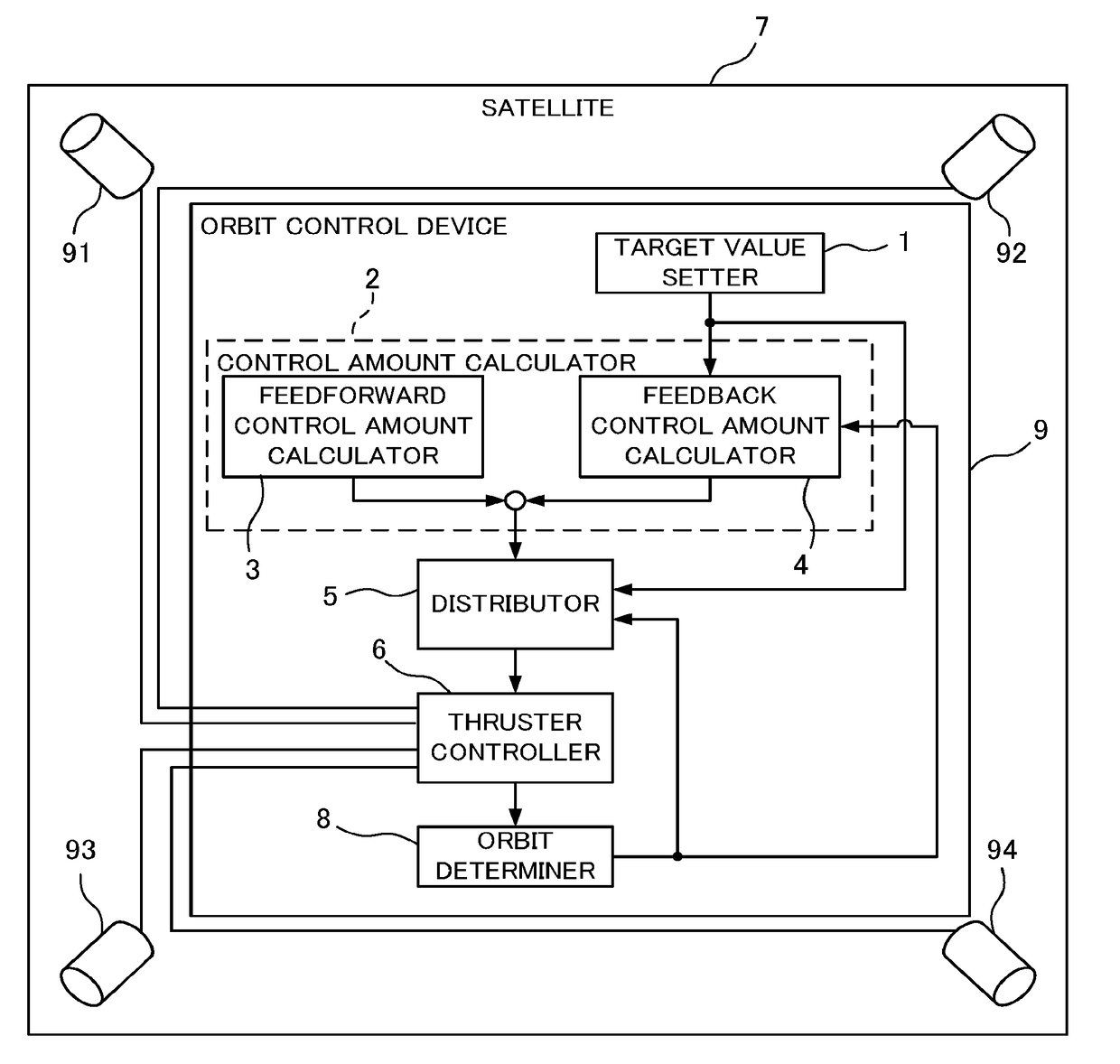
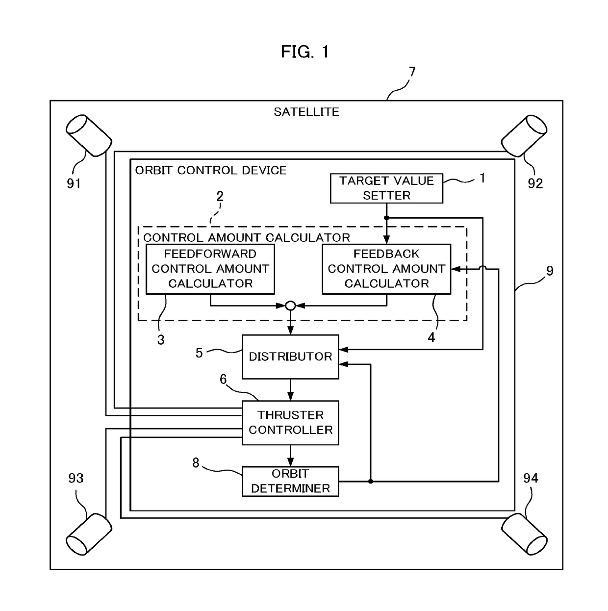
[0018]FIG. 1 is a block diagram illustrating a configuration of a satellite orbit control device according to Embodiment 1 of the present disclosure. An orbit control device 9 is mounted on a satellite 7. In embodiments, the satellite 7 is assumed to be a geostationary satellite. The satellite 7 includes four thrusters 91, 92, 93, and 94 and the orbit control device 9 controlling them. The orbit control device 9 includes a target value setter 1, a control amount calculator 2, a distributor 5, an orbit determiner 8, and a thruster controller 6. The control amount calculator 2 includes a feedforward control amount calculator 3 and a feedback control amount calculator 4. The orbit control device 9 determines a firing timing and a firing amount of each of the thrusters 91, 92, 93, and 94 for keeping the orbit of the satellite 7 and controls the thrusters 91, 92, 93, and 94 to fire with the determined firing timings and firing amounts.
[0019]In the orbit control device 9 of Embodiment 1, ...
embodiment 2
[0085]In Embodiment 2, a feasible timing of firing the thrusters in one orbit period is preset. Then, the second to fourth thruster firing amounts and whether the firing is possible are determined based on the control amounts of the mean eccentricity vector and the mean inclination vector calculated for each timing by the control amount calculator. The configuration of Embodiment 2 is the same as that of Embodiment 1; only operation of the distributor 5 of the orbit control device 9 is different. The others, namely the target value setter 1, the control amount calculator 2, the thruster controller 6, and the orbit determiner 8, are the same as those in Embodiment 1.
[0086]The distributor 5 receives, as in Embodiment 1, the control amounts of the mean eccentricity vector and the mean inclination vector calculated by the control amount calculator 2, the target value of the mean ground longitude set by the target value setter 1, and the mean orbital elements and the temporal change rate...
embodiment 3
[0107]In Embodiment 3, two of the four thrusters are combined to perform the south-north control one time in one orbit period and two thrusters are combined to perform the east-west control two times in one orbit period. The configuration of Embodiment 3 is the same as that of Embodiment 1; only operation of the distributor 5 of the orbit control device 9 is different. The others, namely the target value setter 1, the control amount calculator2, the thruster controller 6, the satellite 7, and the orbit determiner 8, are the same as those in Embodiment 1. Distributor 5 is the only component different from that in Embodiment 1; therefore, the distributor 5 is described.
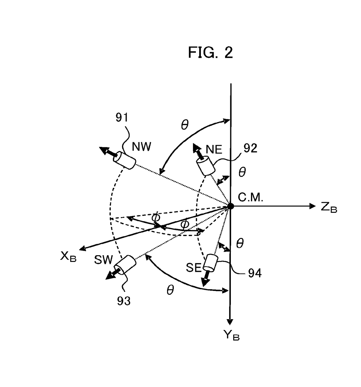
[0108]The firing amounts of the thrusters, the thruster 91 (NW thruster), the thruster 92 (NE thruster), the thruster 93 (SW thruster), and the thruster 94 (SE thruster), illustrated in FIG. 2 are denoted by fNW, fNE, fSW, and fSE, respectively. On the premise that two thrusters are fired simultaneously, the northward f...
PUM
 Abstract
Description
Claims
Application Information
 - R&D
- Intellectual Property
- Life Sciences
- Materials
- Tech Scout
- Unparalleled Data Quality
- Higher Quality Content
- 60% Fewer Hallucinations
Browse by: Latest US Patents, China's latest patents, Technical Efficacy Thesaurus, Application Domain, Technology Topic, Popular Technical Reports.
© 2025 PatSnap. All rights reserved.Legal|Privacy policy|Modern Slavery Act Transparency Statement|Sitemap|About US| Contact US: help@patsnap.com


