
Ink jet recording method, recording head, and ink jet recording apparatus

a recording method and ink jet technology, applied in the field of ink jet recording methods, can solve problems such as difficult auxiliary ejection, and achieve the effect of satisfying the stability of intermittent ink ejection

Active Publication Date: 2017-12-21
CANON KK
View PDF4 Cites 0 Cited by
  • Summary
  • Abstract
  • Description
  • Claims
  • Application Information

AI Technical Summary

Benefits of technology

This patent provides an ink jet recording method that can reliably eject ink even under severe conditions, such as when using a line head. The method also provides a recording head and an ink jet recording apparatus that use this method.

Problems solved by technology

Since the ejection orifices are arranged across the entire width of the recording medium, auxiliary ejection is difficult.
However, the intermittent ejection stability of any structure disclosed in the above-cited patent documents Japanese Patent Laid-Open No. 2007-118611, PCT Japanese Translation Patent Publication No. 2013-522414, and Japanese Patent Laid-Open No. 2011-202088 is insufficient.

Method used


Image

  • Ink jet recording method, recording head, and ink jet recording apparatus
  • Ink jet recording method, recording head, and ink jet recording apparatus
  • Ink jet recording method, recording head, and ink jet recording apparatus

Examples


examples

[0053]The subject matter of the present disclosure will be further described in detail with reference to the following Examples and Comparative Examples. However, it is not limited to the Examples, nor particularly limited unless departing from the scope and spirit of the disclosure. In the following description, “part(s)” and “%” are on a mass basis unless otherwise specified.

Preparation of Pigment Dispersion Liquid A

[0054]Into the solution of 5.00 g of concentrated hydrochloric acid in 5.50 g of water, 4.00 g of 4-aminophthalic acid was added at 5° C. To the resulting solution being stirred in an ice bath to keep the temperature at 10° C. or less, the solution of 1.80 g of sodium nitrite in 9.00 g of water was added. After stirring for 15 minutes, 6.00 g of a carbon black having a specific surface area of 220 m2 / g and a DBP absorption of 105 mL / 100 g was added. After stirring for another 15 minutes, the resulting slurry was filtered through No. 2 filter paper (manufactured by Adva...


PUM


Abstract

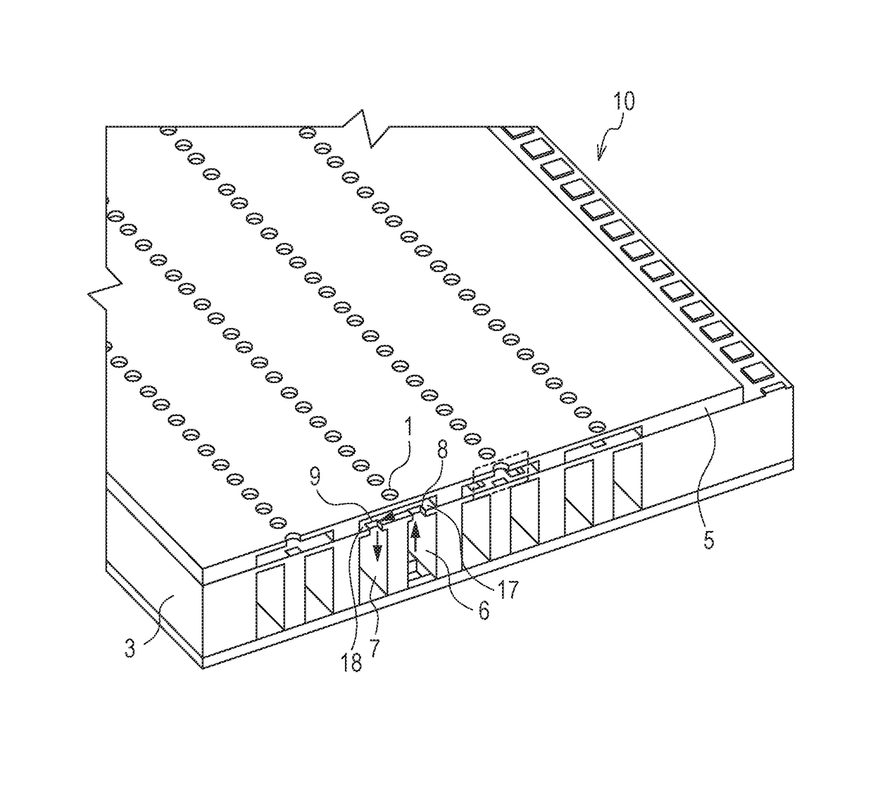
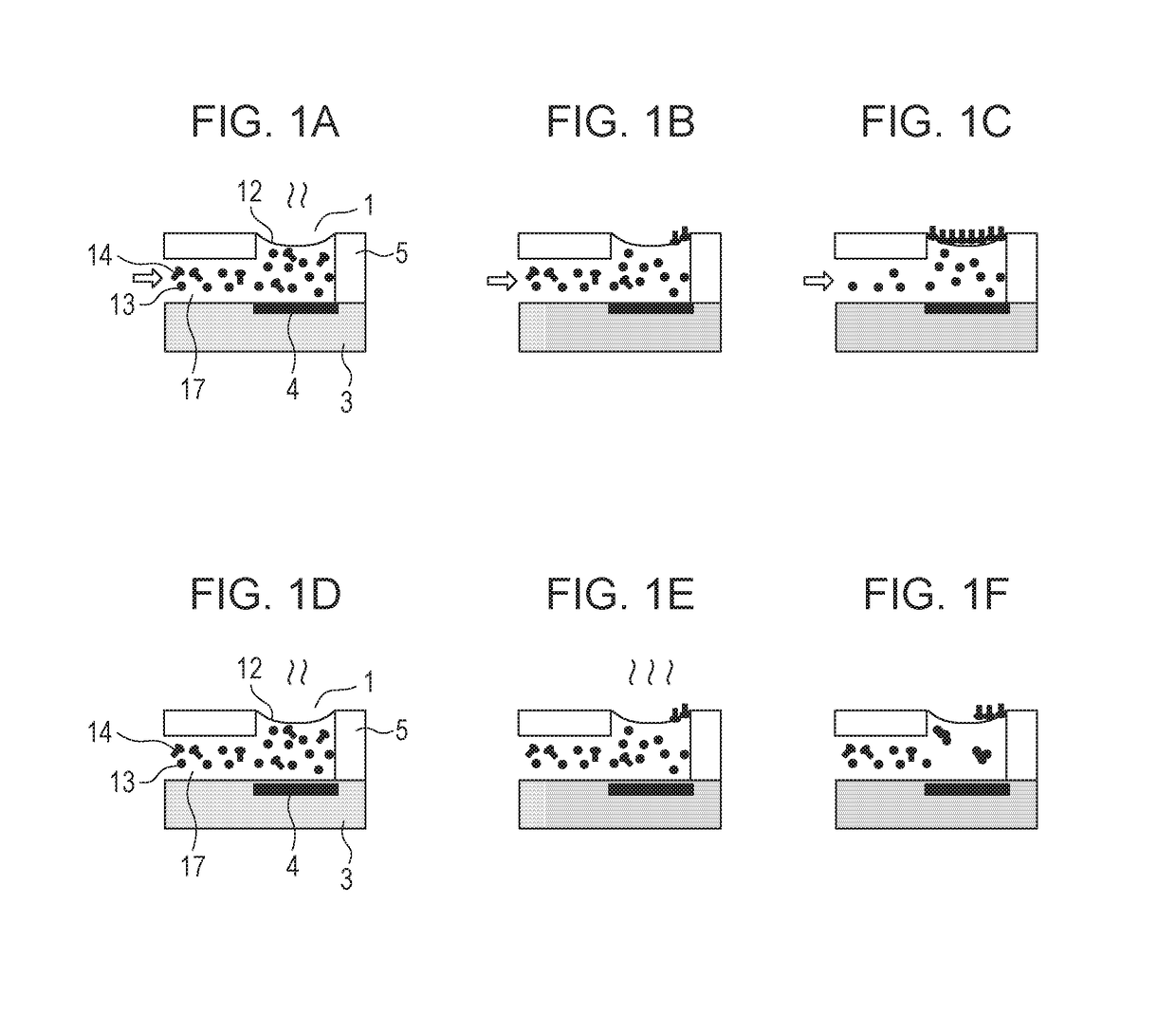
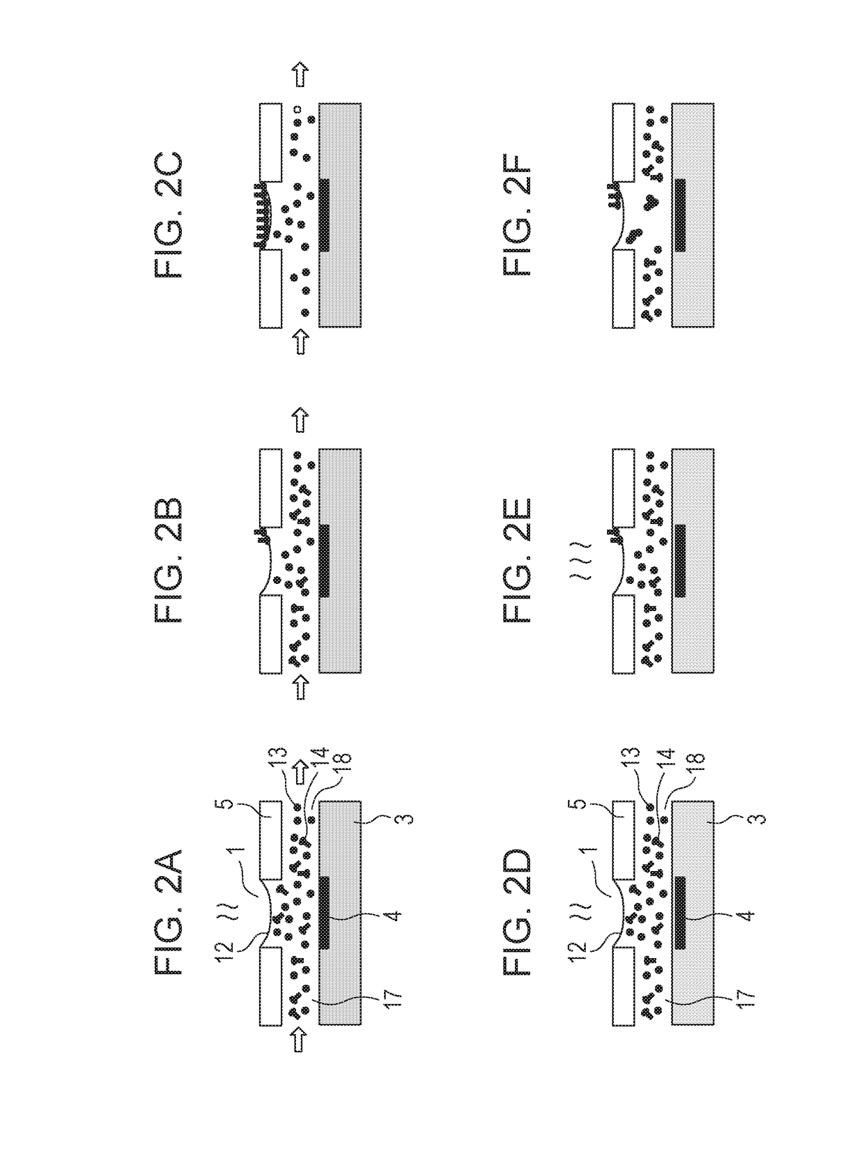
An ink jet recording method is provided for recording an image by ejecting an ink from a recording head including a member defining an ejection orifice through which the ink is ejected, an ejection element configured to generate an energy used for ejecting the ink, and a first flow path communicating with a portion between the ejection orifice and the ejection element. The method includes ejecting an ink through the ejection orifice, and moving the ink from the first flow path to the portion between the ejection orifice and the ejection element separately from the ejecting of the ink. In this method, the ink is an aqueous ink containing a coloring material and a compound containing a chain hydrocarbon having a carbon number of 8 or more to 18 or less substituted by a hydroxy group or an anionic group.

Description

BACKGROUND OF THE INVENTIONField of the Invention[0001]The present disclosure relates to an ink jet recording method, a recording head, and an ink jet recording apparatus.Description of the Related Art[0002]Ink jet recording apparatus including a line recording head (line head) are being used for high-speed image recording (see PCT Japanese Translation Patent Publication No. 2002-533247). A line head has ejection orifices through which an ink is ejected. Since the ejection orifices are arranged across the entire width of the recording medium, auxiliary ejection is difficult. Auxiliary ejection is one of the operations for recovering the function of the ejection orifices and is intended to suppress the increase in viscosity of the ink in ejection orifices the ejection frequency of which is low and thus to prevent the degradation of ejection properties. It is known that ink is moved in the vicinity of the ejection orifices to reduce or eliminate the clogging of the ejection orifices w...

Claims


Application Information

Patent Timeline
IPC IPC(8): B41J2/14
CPCB41J2/1433B41J2/14032B41J2/1404C09D11/06C09D11/322C09D11/38B41J2202/12B41J2002/14403C09D11/108
Inventor SANADA, MIKIOOKUSHIMA, SHINGONAKAGAWA, YOSHIYUKI
Owner CANON KK
Learn More