
Airfoil cooling passageways for generating improved protective film

Active Publication Date: 2017-12-14
ANSALDO ENERGIA SWITZERLAND AG
View PDF2 Cites 6 Cited by
  • Summary
  • Abstract
  • Description
  • Claims
  • Application Information

AI Technical Summary

Benefits of technology

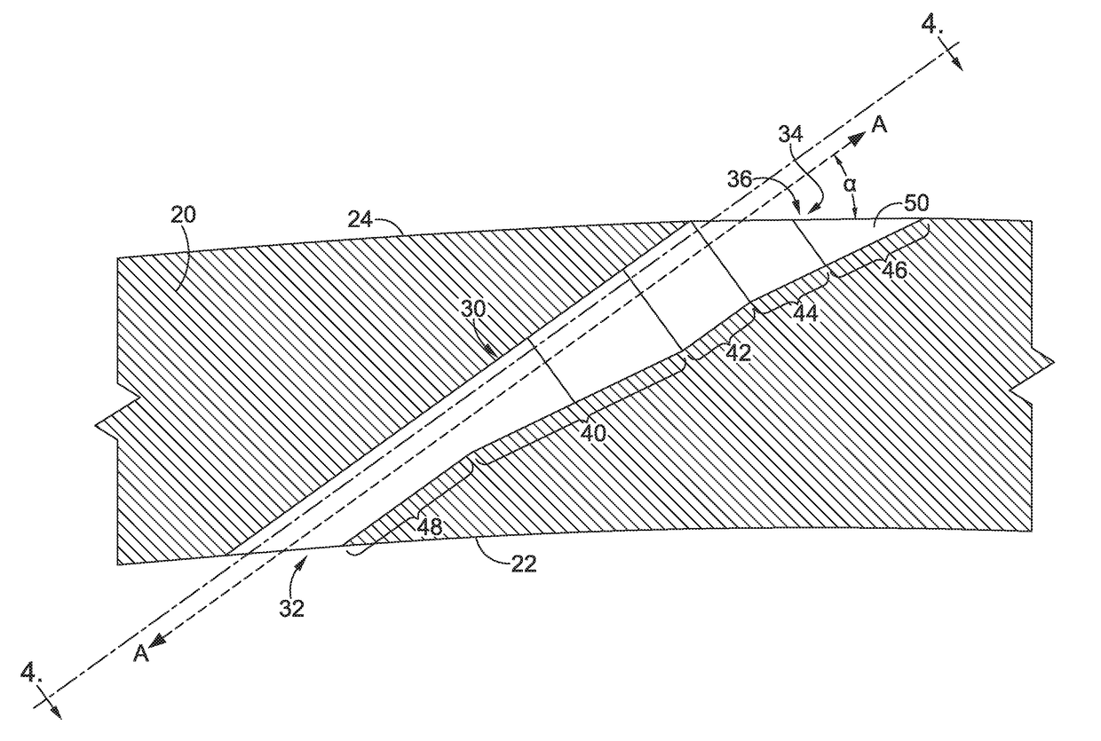
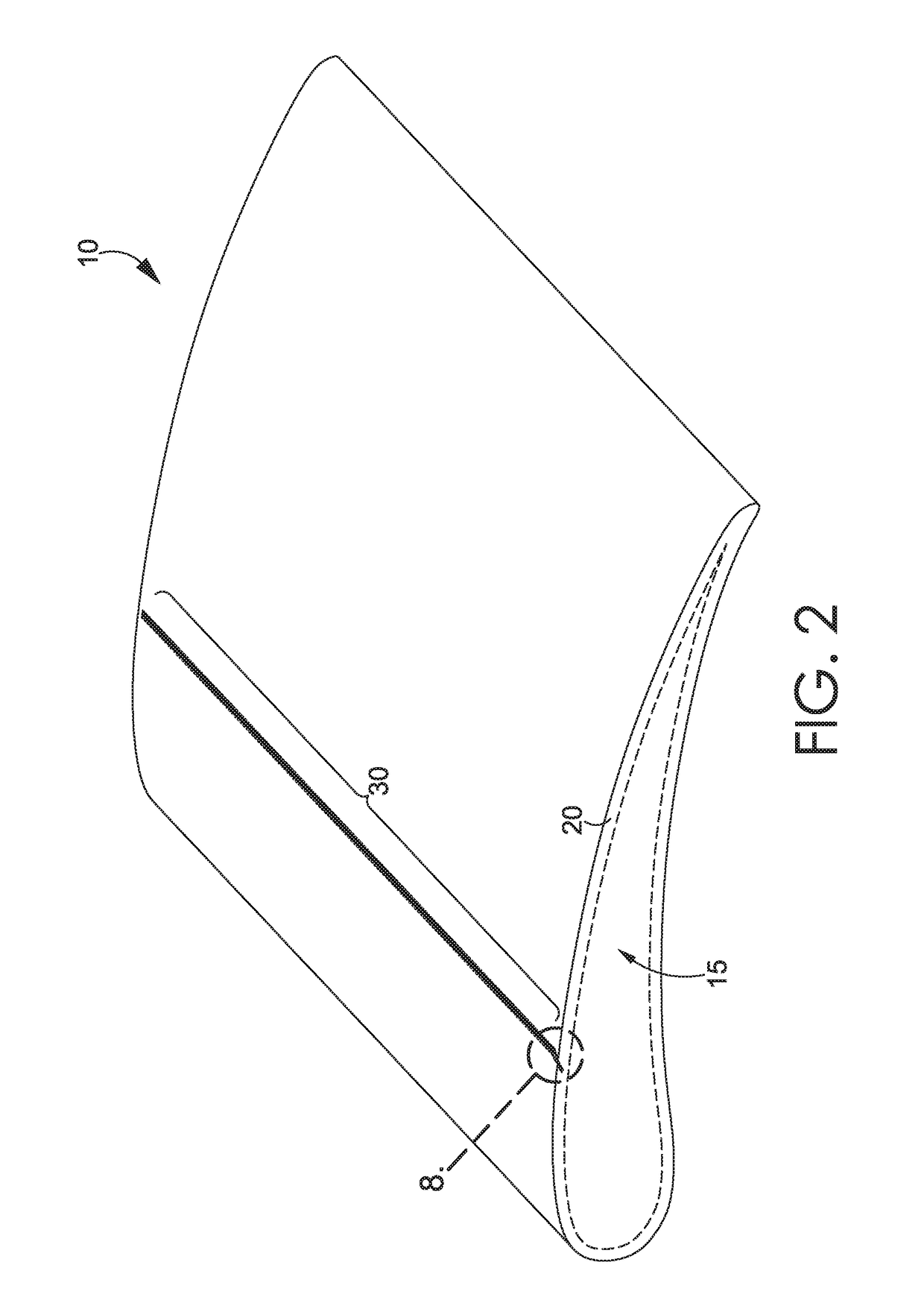
The present invention provides an improved cooling hole in a gas turbine engine turbine airfoil. The cooling hole has multiple cavities, including a flow controlling cavity, a diffusing cavity, and an edge cavity. The flow controlling cavity has a constant cross-sectional area, while the diffusing cavity and edge cavity have cross-sectional areas that decrease towards each other. The cooling fluid flows through these cavities and forms a protective film on the airfoil wall, improving its cooling performance. The improved cooling hole design also reduces the tolerance stack associated with the minimum distance between cooling passages, allowing for closer positioning of cooling passages and improving coverage and uniformity of the cooling fluid film.

Problems solved by technology

The intersection of these portions of emitted cooling fluids would cause increased turbulence in the emitted cooling fluid, which is undesirable for forming a uniform protective layer of film between the hot combustion gases and the second, exterior surface 24A.

Method used


Image

  • Airfoil cooling passageways for generating improved protective film
  • Airfoil cooling passageways for generating improved protective film
  • Airfoil cooling passageways for generating improved protective film

Examples


Embodiment Construction

[0020]The subject matter of the present invention is described with specificity herein to meet statutory requirements. However, the description itself is not intended to limit the scope of this patent. Rather, the inventors have contemplated that the claimed subject matter might also be embodied in other ways, to include different steps or combinations of steps similar to the ones described in this document, in conjunction with other present or future technologies. Moreover, although the terms “step” and / or “block” might be used herein to connote different elements of methods employed, the terms should not be interpreted as implying any particular order among or between various steps herein disclosed unless and except when the order of individual steps is explicitly stated.

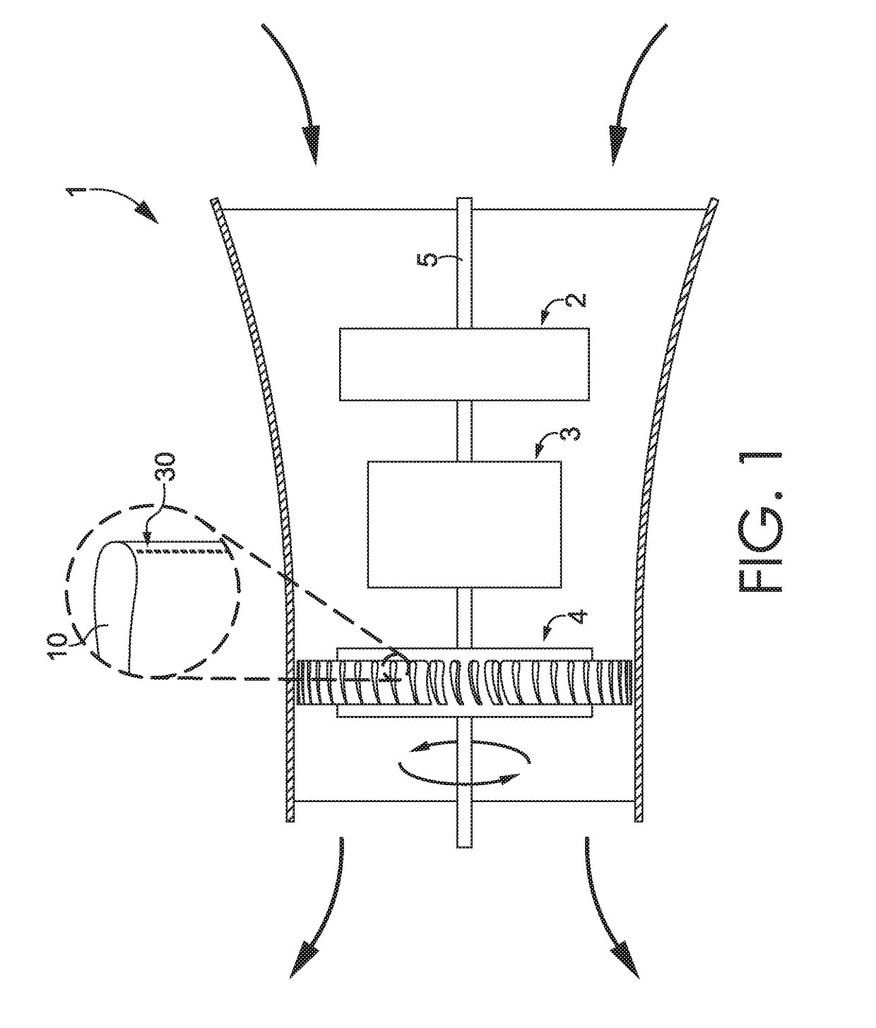
[0021]Referring initially to FIG. 1, a simplified gas turbine engine 1 is depicted. The gas turbine engine 1 includes a compressor 2, a combustor 3, and a turbine 4. In some embodiments, the compressor 2 compresse...


PUM


Abstract

An airfoil for a gas turbine engine, the airfoil comprising a wall having a first surface, a second surface, and a passageway extending through the wall from a first opening in the first surface to a second opening in the second surface, the passageway having one or more sections between the first opening and the second opening, the one or more sections in fluid communication with each other, the plurality of sections comprising a first diffuser section providing a first change in cross-sectional area within the passageway, a second diffuser section providing a second change in cross-sectional area within the passageway, a flow conditioning section, and an edge section having two surfaces set opposite each other across the passageway, the two surfaces extending along the passageway substantially in parallel to one another, the edge section being located adjacent to the second opening.

Description

FIELD[0001]The present invention relates to improved cooling passageways formed in airfoils of a gas turbine engine and a method of manufacturing the improved cooling passageways.BACKGROUND[0002]In a typical operation of a gas turbine engine, the combustor generates high temperature combustion gases that pass through a turbine having a plurality of airfoils. In order to protect these airfoils from the extreme temperatures of the combustion gases, a variety of cooling techniques have been developed. For instance, a plurality of cooling holes may be formed in an outer surface of the turbine airfoil. These cooling holes are adapted to communicate a cooling fluid (e.g., air or steam) from an inner reservoir within the turbine airfoil to the exterior surface of the turbine airfoil. The high velocity of the high temperature combustion gases causes the emitted cooling fluid to wrap over the outer surface of the turbine airfoil and create a thin, protective film layer of cooling fluid betwe...

Claims


Application Information

Patent Timeline
IPC IPC(8): F01D5/18F01D9/04F01D25/12
CPCF01D5/186F01D9/041F01D25/12F05D2240/30F05D2230/12F05D2240/11F05D2220/32F05D2260/202F05D2250/00
Inventor TORKAMAN, ALEXVOGEL, GREGORYJOHNSTON, CHRISTOPHERBORJA, MICHELE
Owner ANSALDO ENERGIA SWITZERLAND AG
Learn More