
Woven fabric, method for manufacturing design woven fabric and method for manufacturing interior material

a technology of woven fabric and interior material, which is applied in the direction of light-guided instruments, lighting and heating equipment, and fibre light guides, etc., can solve the problems of optical fiber damage risk, and achieve the flexibility of the longitudinal direction of the non-light-guiding yarn, and the flexibility of the entire textile

Active Publication Date: 2017-11-30
TOYOTA BOSHOKU KK +1
View PDF37 Cites 9 Cited by
  • Summary
  • Abstract
  • Description
  • Claims
  • Application Information

AI Technical Summary

Benefits of technology

The present invention provides a woven fabric that protects optical fiber yarns during processing and allows easy exposure of the optical fiber yarns when protection becomes unnecessary. The woven fabric also includes a back protecting layer that functions as a protecting layer for the optical fiber layer to prevent thermal damage and contamination during the manufacturing process. The technical effects achieved by this invention include improved protection and easy exposure of optical fiber yarns in a woven fabric, which facilitates the use of optical fiber in design woven fabrics and interior materials.

Problems solved by technology

However, labor and time are required to pull out the other constituent yarns interlaced with the optical fibers in the woven fabric, and there is a risk of damaging the optical fibers when pulling out the other constituent yarns.

Method used


Image

  • Woven fabric, method for manufacturing design woven fabric and method for manufacturing interior material
  • Woven fabric, method for manufacturing design woven fabric and method for manufacturing interior material
  • Woven fabric, method for manufacturing design woven fabric and method for manufacturing interior material

Examples


embodiment 1

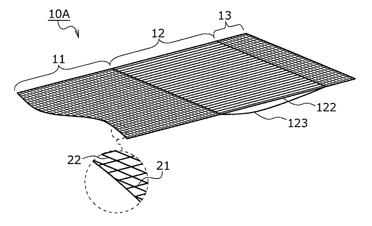
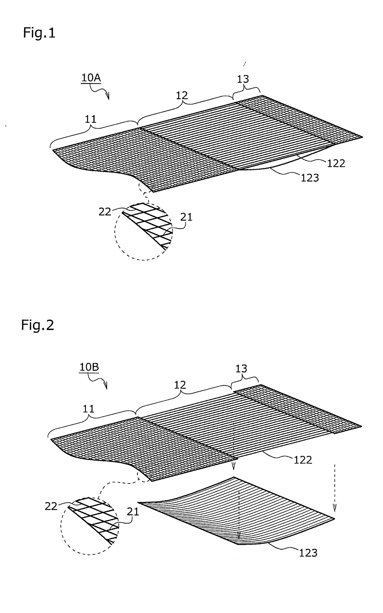
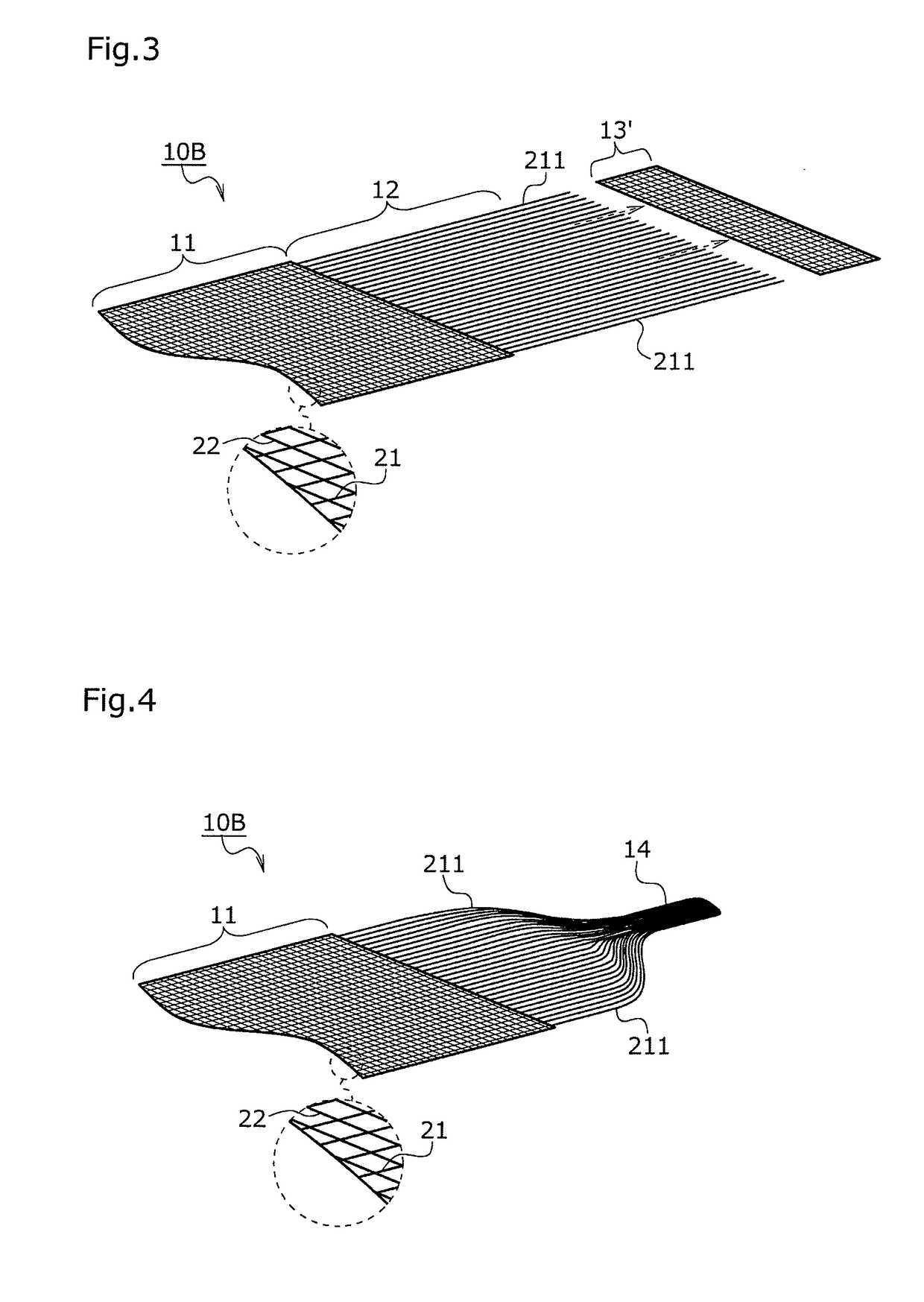
[0118]The woven fabric 10A shown in FIG. 1 is a woven fabric woven from a first constituent yarn 21 as a warp and a second constituent yarn 22 as a weft. However, it is not limited which of the first and second constituent yarns 21 and 22 is the warp and which of the first and second constituent yarns 21 and 22 is the weft.

[0119]The first constituent yarn 21 comprises an OF yarn 211 (side emission type optical fiber yarn) and a non-light guiding yarn 212. On the other hand, the second constituent yarn 22 consists only of a non-light guiding yarn 222. The non-light guiding yarns 212 and 222 are light shielding yarns which can exert the light shielding performance to the OF yarns 211, and the non-light guiding yarn 212 is configured to have fineness smaller than that of the non-light guiding yarn 222.

[0120]The woven fabric 10A has a first region 11 in which the first constituent yarn 21 and the second constituent yarn 22 are woven in one layer. The first region 11 is a design region. ...

embodiment 2

[0127]A woven fabric 10A shown in FIG. 5 is different from the woven fabric 10A of Embodiment 1 in comprising a front protecting layer 121, and is identical therewith in other respects.

[0128]The woven fabric 10A has a second region 12 positioned adjacent to the first region 11. In the second region, the first and second constituent yarns 21 and 22 are woven in three separable layers. The three separable layers are laminated in the order of: the front protecting layer 121, the optical fiber layer 122 and the back protecting layer 123. These three layers are formed by double weaving, and the front and back protecting layers 121 and 123 are woven from the non-light guiding yarns 212 and 222, respectively. Also, the optical fiber layer 122 is a layer formed only of the OF yarns 211.

[0129]In FIG. 5, the front protecting layer 121 and the back protecting layer 123 are expressed in forms loosened to the design surface side and to the non-design surface side, respectively, for convenience s...


PUM

PropertyMeasurementUnit
diameteraaaaaaaaaa
diameteraaaaaaaaaa
diameteraaaaaaaaaa

Abstract

A woven fabric includes a first constituent yarn having an optical fiber yarn and a non-light guiding yarn and a second constituent yarn having a non-light guiding yarn. The woven fabric has a first region in which the first and second constituent yarns are woven in one layer and a second region which is positioned adjacent to the first region and in which the first and second constituent yarns and are woven in two or more separable layers. The woven fabric has an optical fiber layer and a back protecting layer as the separable layers. The optical fiber layer is a layer formed of the optical fiber yarns. The back protecting layer is a layer in which the non-light guiding yarn of the first constituent yarn and the non-light guiding yarn of the second constituent yarn are woven. Further, the woven fabric can further comprise a front protecting layer.

Description

CROSS-REFERENCE TO RELATED APPLICATIONS[0001]The present application claims priority under 35 U.S.C. §119 of Japanese Application No. 2016-105666 filed on May 26, 2016, the disclosure of which is expressly incorporated by reference herein in its entirety.BACKGROUND1. Technical Field[0002]The present invention relates to a woven fabric, a method for manufacturing a design woven fabric, and a method for manufacturing an interior material. More specifically, the invention relates to a woven fabric comprising an optical fiber as a constituent yarn, a method for processing this woven fabric into a design woven fabric, and a method for manufacturing an interior material comprising this design woven fabric as a design layer.2. Related Art[0003]Conventionally, woven fabrics comprising an optical fiber that is capable of side emission, as a constituent yarn, have been proposed. Once light is made incident on this woven fabric from one end, the incident light is leaked from an optical fiber s...

Claims


Application Information

Patent Timeline
Patent Type & Authority Applications(United States)
IPC IPC(8): D03D15/00F21V8/00
CPCD03D15/00D10B2401/20G02B6/0005G02B6/001F21V2200/15D03D3/06D03D11/02D03D15/547D03D15/283
Inventor YAMADA, TAKAMASAOKAHARA, SHINGOSAKOH, MITSUTAKAKANAMORI, HIDEOITO, ATSUHIKOYAMAMOTO, TAKAYOSHI
Owner TOYOTA BOSHOKU KK
Learn More