
Modular, submersible ultrasonic tubular transducer

a tubular transducer, submerged technology, applied in piezoelectric/electrostrictive resonant transducers, sound producing devices, chemical/physical/physicochemical processes, etc., to achieve the effect of reducing the number of vibration nodes, improving the homogeneity of the acoustic field, and reducing the vibration at the end

Active Publication Date: 2017-11-30
CEDRAT TECH
View PDF0 Cites 6 Cited by
  • Summary
  • Abstract
  • Description
  • Claims
  • Application Information

AI Technical Summary

Benefits of technology

The patent describes a device that reduces the radial vibration of a tube when a transducer is connected to it. The device has a sealed tube that protects the transducer and allows it to be immersed. The device also has a common electronic circuit that reduces the number of cables needed to power each module. This results in a more uniform distribution of vibration and a more efficient system overall.

Problems solved by technology

When the latter exceed the static pressure, they cause cavitation.
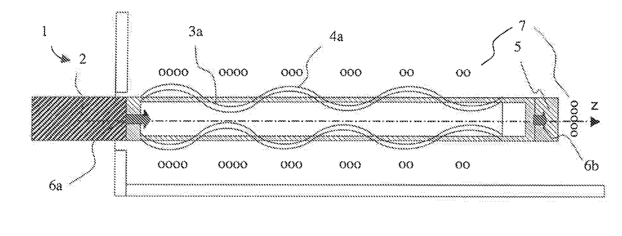
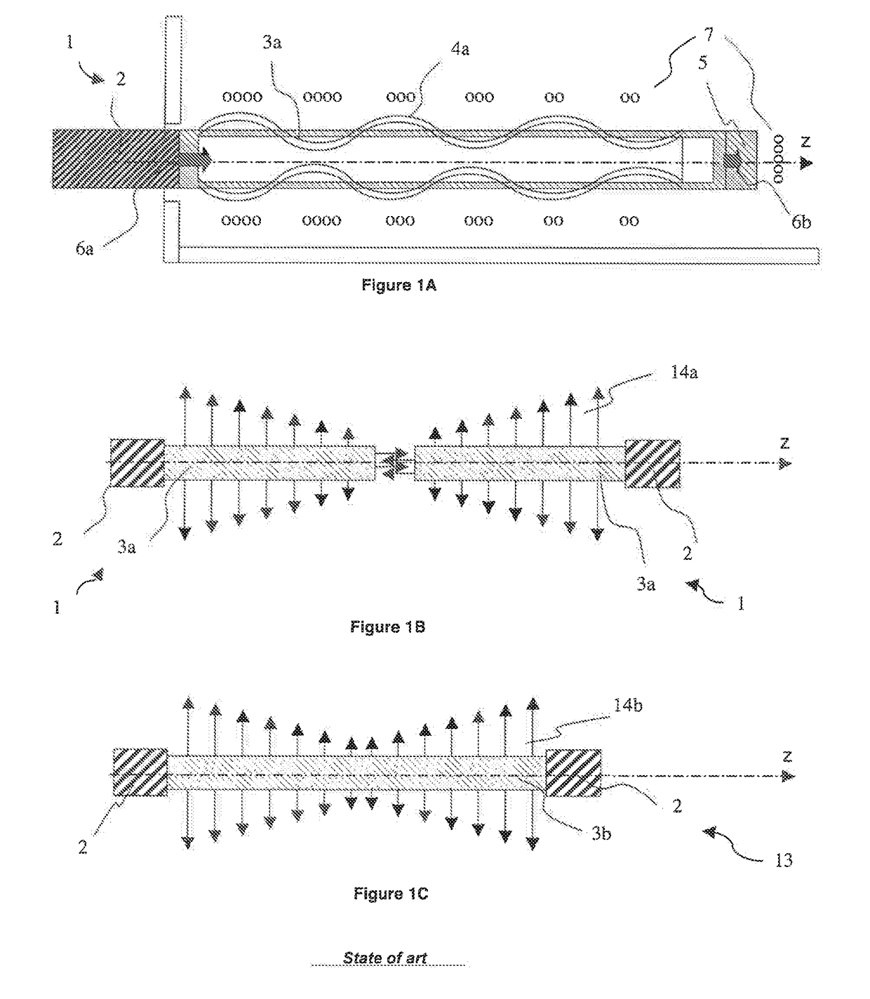
Nevertheless, it is not possible to fit two transducers in series, as the axial cavitation produced will disturb or even damage the transducer located nearby.
The known transducer is therefore not optimized to produce radial vibrations, which reduces the efficiency of methods based on the use of acoustic energy located around the tube.
In addition, on account of the fact that excitation of the tube is performed on one side of the tube, the radial vibration along the tube is not symmetrical with respect to a plane perpendicular to the axis and passing via the centre of the tube.
The vibration generated in this way presents a drawback as the distance between the vibration nodes is about 12 to 14 cm for a tube.
This large half wavelength therefore causes a low homogeneity of the cavitation area which is detrimental when performing treatment of the surface involved.
In an application such as deposition on textile, this results in an irregularity of the deposition and therefore a poor treatment quality.
Furthermore their drawbacks remain that only the sonotrode is submersible and that the transducer cannot be used to produce a sonochemical treatment for large parts with a length of more than 1.5 m at 25 kHz.
It is not possible to fit several transducers in series as the converters are not submersible and their longitudinal vibrations in the axis of the transducer would produce detrimental effects on the nearby adjacent transducer.
On account of this limitation in dimension and homogeneity, it is not possible to process large parts easily.
Although it is theoretically efficient, this solution requires the use of costly and complex electronics.
It does not solve the problem of treatment of large dimensions.
In addition, this concept does not enable any modularity to be envisaged to deal with the problem of length of the transducer and of treatment of large parts.
In both the documents, the transducer is not submersible and is not able to be used in series to treat large parts.
This effect is not desirable when the acoustic energy has to be concentrated radially around the transducer, all the more so as it consumes electric power unnecessarily.
In addition, this scheme does not take account of the large amount of parasite vibratory waves transmitted by the ends of each transducer to the transducer opposite it.
The above-mentioned state of the art highlights the following limitations for existing tubular transducers:Structure not totally submersible, not enabling implementation on large structures and in homogeneous manner.Length limited to 0.7 m in general and to about 1.5 m in the case of the push-pull transducer (document U.S. Pat. No. 5,200,666), which does not enable treatment of large parts, economically pertinent in the textile industry for example (width of 2 to 4 m),Non-homogeneous acoustic field along the transducer, conditioned by the resonance frequency and the dimensions of the tube, with in particular vibration nodes and antinodes located far from one another and a large decrease between the converter and the free end, which does not ensure a treatment homogeneity necessary for surface treatment applications for example.Impossibility of completely immersing the electromechanical converter which considerably reduces the efficiency of the installation and which therefore increases the operating cost.
This results in a maximum radial vibration of the tube.

Method used


Image

  • Modular, submersible ultrasonic tubular transducer
  • Modular, submersible ultrasonic tubular transducer
  • Modular, submersible ultrasonic tubular transducer

Examples


Embodiment Construction

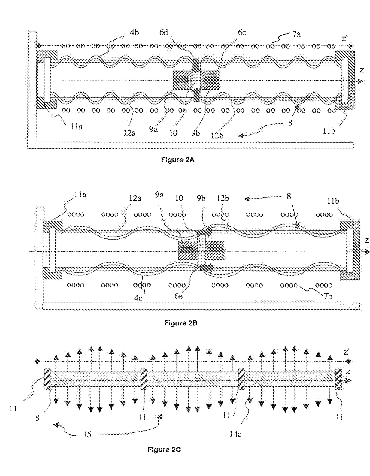
[0070]FIGS. 2A and 2B represent a symmetrical transducer (8) according to the invention illustrating two different operating modes.

[0071]In a first operating mode (FIG. 2A), called radial mode, the symmetrical transducer (8) is composed of two symmetrical electromechanical converters (9a, 9b), a coupler (10) and a tubular structure (12a, 12b) designed for radial acoustic generation. The two converters are placed along a z-axis, symmetrically on each side of the coupler (10), which is located in the central plane of the tubular structure (12a, 12b), formed by two adjoined tubes (12a, 12b) and aligned on the z-axis.

[0072]The two converters (9a, 9b) are excited in phase, which produces axial expansion vibrations (6c) in compression on the coupler (10). This device will then convert the axial vibration (6c) into radial vibration (6d). This radial vibration (6d) enables the radial vibration mode (4b) of the tubular structure (12a, 12b), designed for radial acoustic generation, to be exci...


PUM


Abstract

The ultrasonic tubular transducer is activated at the centre thereof by two symmetrical electromechanical converters. The vibration generated by the two electromechanical converters is converted and then transmitted to the tube via a coupler. The ultrasonic transducer can be vibrationally isolated from the interfaces thereof by caps equally suitable for connecting the transducer to a stationary frame, a free end or another similar ultrasonic transducer. A device for pre-stressing electromechanical converters has a hole bored at the centre thereof in order to allow cables from the transducer as well as from adjacent transducers to pass therethrough.

Description

BACKGROUND OF THE INVENTION[0001]The invention relates to an ultrasonic tubular transducer to propagate acoustic waves in a fluid medium, and comprising:[0002]an electromechanical conversion device with active elements associated with at least one metal tube transmitting the vibrations to the fluid medium,[0003]a transmission system of the vibrations between the conversion device and the tube,[0004]and a device for pre-stressing the active elements of said conversion device.[0005]Tubular ultrasonic transducers enable radial vibrations to be created and waves able to cause cavitation to be propagated in media, in particular fluid media, and find their applications in precision cleaning or sonochemistry, such as extraction of substances or of particle deposition. Their purpose is in particular to generate ultrasounds:[0006]within the fluid and in proximity to the surface to be treated to maximize the efficiency of the installation,[0007]over the whole of the surface to be treated, whi...

Claims


Application Information

Patent Timeline
Patent Type & Authority Applications(United States)
IPC IPC(8): B06B1/06G10K15/04G10K11/24H04R17/10B08B3/12H10N30/88H10N30/20
CPCB06B1/0618G10K15/043B08B3/12H04R17/10G10K11/24B01J19/10B06B3/00
Inventor FORISSIER, TIMOTHEEBENCHEIKH, NABILCLAEYSSEN, FRANKPAGES, ALEXANDRE
Owner CEDRAT TECH
Learn More