X-ray generation tube, x-ray generation apparatus, and radiography system
a technology of x-ray generation and x-ray tube, which is applied in the direction of x-ray tube details, x-ray tube targets and convertors, x-ray tubes, etc., can solve the problems of limiting the heat transfer quantity and restricting the life of the transmission targ
- Summary
- Abstract
- Description
- Claims
- Application Information
AI Technical Summary
Benefits of technology
Problems solved by technology
Method used
Image

Examples
first embodiment
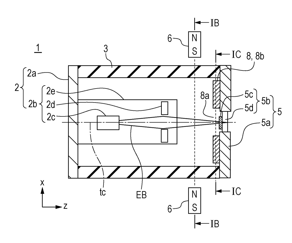
[0021]FIGS. 1A to 1C, 5A, and 5B are schematic diagrams for describing an X-ray generation tube 1 in a first embodiment of the present disclosure.
[0022]The X-ray generation tube 1 includes an enclosure made up of a cathode 2, an anode 5, and an insulating tube 3. The inside of the enclosure is exhausted to a vacuum and its airtightness is retained to have a longer mean free path of electrons than the distance between an electron emission portion and a target.
>
[0023]The cathode 2 is an electrode that defines a cathode potential of the X-ray generation tube 1 by the inclusion of a conductive cathode member 2a connected to the insulating tube 3 and an electron gun 2b and is also a structural component in the enclosure. The electron gun 2b includes a conductive tubular member 2e connected to the cathode member 2a, an electron emission portion 2c, and an electrostatic lens electrode 2d, which are disposed in the tubular member 2e. The electron emission portion 2c and electrostatic lens e...
second embodiment
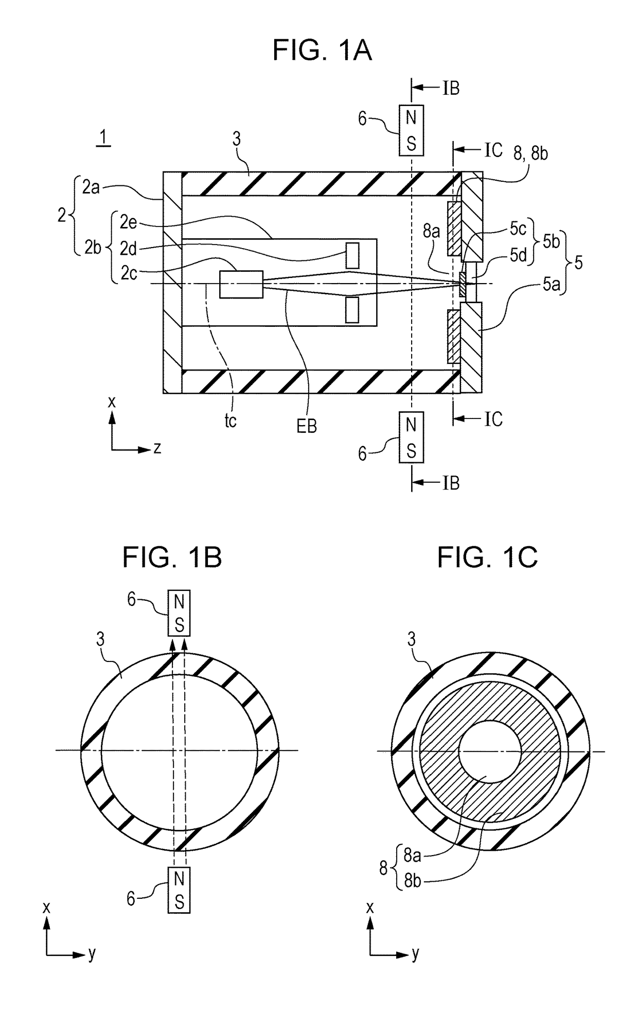
[0054]FIGS. 2A to 2C are schematic diagrams for describing the X-ray generation tube 1 according to a second embodiment of the present disclosure. The second embodiment differs from the first embodiment in that when seen along the tube axial direction, the magnetic shielding portion 8 includes portions 16a and 16b overlapping the magnetic deflection portions 6 in the tube radial direction, as illustrated in FIGS. 2A to 2C. The overlapping portions 16a and 16b are hermetically connected to the insulating tube 3.
[0055]In the present embodiment, as illustrated in FIGS. 2A to 2C, the magnetic shielding portion 8 includes the overlapping portions 16a and 16b, which overlap the magnetic deflection portions 6 along the tube radial direction. This leads to the magnetic shielding effect larger than that in the first embodiment. The position stability of the X-ray generation source can be further enhanced independently of the relative permeability of the subject 9, the position of photographi...
third embodiment
[0056]FIGS. 3A to 3C are schematic diagrams for describing the X-ray generation tube 1 according to a third embodiment of the present disclosure. The third embodiment is the same as the first embodiment, except that the anode member 5a is made of a material with a magnetic shielding property, as illustrated in FIGS. 3A to 3C.
[0057]The magnetic shielding portion 8 relates to the anode 5 in the first to third embodiments. It may be an intermediate electrode (not illustrated) insulated from the anode member. In the form in which the magnetic shielding portion is insulated from the anode member, the magnetic shielding portion may be arranged inside the enclosure and arranged closer to the electron emission portion than the anode member in the tube axial direction to suppress discharging.
PUM
| Property | Measurement | Unit |
|---|---|---|
| thickness | aaaaa | aaaaa |
| voltage | aaaaa | aaaaa |
| thickness | aaaaa | aaaaa |
Abstract
Description
Claims
Application Information
 - R&D
- Intellectual Property
- Life Sciences
- Materials
- Tech Scout
- Unparalleled Data Quality
- Higher Quality Content
- 60% Fewer Hallucinations
Browse by: Latest US Patents, China's latest patents, Technical Efficacy Thesaurus, Application Domain, Technology Topic, Popular Technical Reports.
© 2025 PatSnap. All rights reserved.Legal|Privacy policy|Modern Slavery Act Transparency Statement|Sitemap|About US| Contact US: help@patsnap.com